Diaphragm compressor with an oblong shaped chamber

a diaphragm compressor and oblong technology, applied in the direction of gas/liquid distribution and storage, working fluid for engines, coatings, etc., can solve the problems of difficulty in holding the compressor head parts together, physical size and energy consumption of such high-pressure compressors, etc., to reduce the wear of the sheet, and reduce the stress of the diaphragm

Pending Publication Date: 2018-05-17
NEL HYDROGEN AS
View PDF5 Cites 5 Cited by
  • Summary
  • Abstract
  • Description
  • Claims
  • Application Information

AI Technical Summary

Benefits of technology

[0041]According to an embodiment of the invention, the coating is made physical vapor deposition or dipping and is selected from the list comprising: diamond like coating, Chromium Nitride coating, silver coating. The coating of the sheets is advantages in that then wear of the sheet is reduced compared to raw non-coated sheets. The coating is therefore an advantageous alternative to introducing lubrication to raw material s...

Problems solved by technology

However when a compressor are to provide a high pressure e.g. starting from above 1 MPa but particularly above 10 MPa the physical size and energy consumption of such high pressure compressors start to increase.
When increasing the volume of...

Method used


Image

  • Diaphragm compressor with an oblong shaped chamber
  • Diaphragm compressor with an oblong shaped chamber
  • Diaphragm compressor with an oblong shaped chamber

Examples


Embodiment Construction

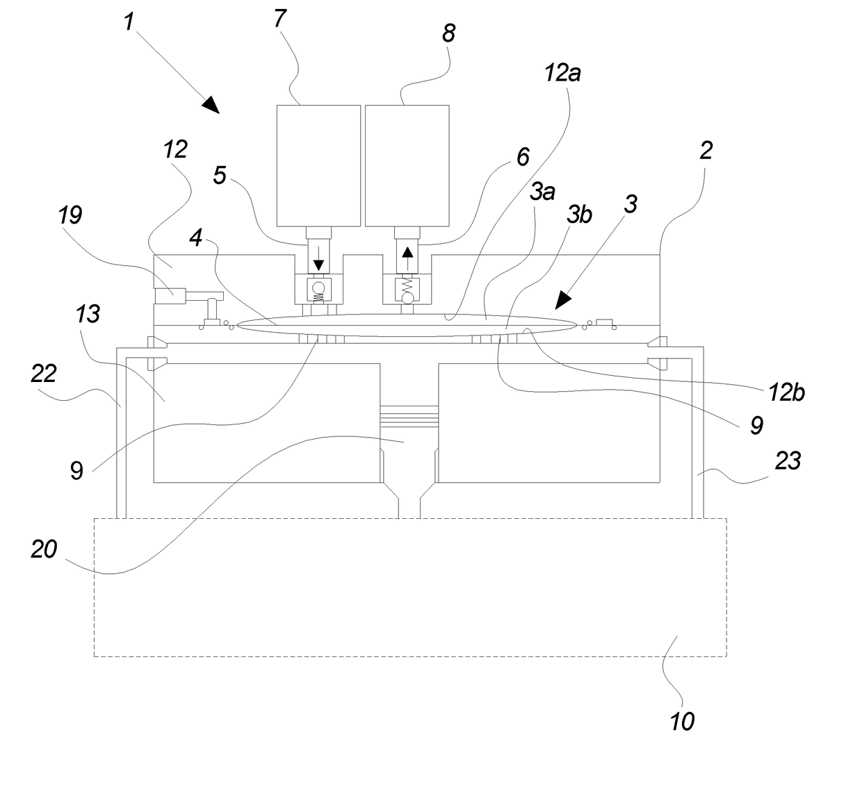
[0058]A schematic overview of a diaphragm pump 1 according to an embodiment of the invention is shown in FIG. 1.

[0059]An upper head 12 and a lower head 13 are assembled to form together a compressor head 2, the joining surfaces of the upper head 3 and the lower head 4, respectively, abutting each other substantially in a plane. Inside the pump head 2, the surfaces of the upper head 3 and the lower head 4, respectively, together form a compressor head chamber 3. This chamber 3 is divided into two compartments by a movable diaphragm 4 arranged in the same plane, in which the upper head 3 and the lower head 4 are assembled to form the pump head 2.

[0060]The compartment between the diaphragm 4 and the upper head 12 is generally referred to as the upper compartment 3a or process fluid chamber. Similarly, the compartment between the diaphragm 4 and the lower head 4 is referred to as the lower chamber 3b or the hydraulic fluid chamber.

[0061]As seen from FIG. 1 a hydraulic system 10 is in fl...


PUM

PropertyMeasurementUnit
Fractionaaaaaaaaaa
Pressureaaaaaaaaaa
Pressureaaaaaaaaaa

Abstract

The invention relates to a high pressure diaphragm compressor for pressurizing a gaseous fluid to a pressure of at least 10 MPa, the compressor including a compressor head having an oblong shaped chamber.

Description

TECHNICAL FIELD[0001]The present invention relates to a high pressure diaphragm compressor comprising a compressor head having an oblong shaped chamber, the use of such compressor in a hydrogen refueling station and a refueling station with such compressor.BACKGROUND[0002]Industrial compressors are known for various different purposes and the pressure ranges of these compressors vary according to the purpose of the compressor. In the same way the design of the compressors are also sometimes customized to a specific purpose. However when a compressor are to provide a high pressure e.g. starting from above 1 MPa but particularly above 10 MPa the physical size and energy consumption of such high pressure compressors start to increase. When increasing the volume of the compressor head, at a point the bolts fastening the two compressor head parts would have difficulties holding the compressor head parts together due to the increased pressure load resulting from the increased volume of th...

Claims


Application Information

Patent Timeline
IPC IPC(8): F04B45/053F04B53/08F04B53/10B32B15/01F17C13/00
CPCF04B45/0533F04B53/08F04B53/10B32B15/01F17C13/002B32B2255/06B32B2255/20F17C2227/0157F17C2221/012F04B39/121F04B43/009F04B45/04Y02E60/32F04B53/14F04B53/16F05B2210/10F17C13/02F04B45/10
Inventor ADAMS, JOSHUA ANDREWMURASHKO, JR., ALEXANDER GEORGEPETERSEN, LEIF KAPPEL
Owner NEL HYDROGEN AS
Why Eureka
Try Eureka