
Display apparatus and backlight unit thereof

Active Publication Date: 2018-05-17
SEOUL SEMICONDUCTOR
View PDF6 Cites 20 Cited by
  • Summary
  • Abstract
  • Description
  • Claims
  • Application Information

AI Technical Summary

Benefits of technology

The patent text describes a display apparatus that uses a direct type backlight to improve uniformity of surface light while reducing the thickness of the apparatus. This is achieved by placing a light source groove in the light guide plate of the backlight unit, allowing for the use of a direct type backlight unit without a separate lens. Additionally, the use of light emitting diode packages with reflectors improves the uniformity of surface light with respect to light emitted from multiple light emitting diode packages. Overall, these technical effects enable a thinner, more uniform display apparatus.

Problems solved by technology

However, a liquid crystal display including such an edge type backlight unit cannot realize high dynamic range (HDR) imaging, which is a method of producing images on a display screen so as to allow a viewer to experience a sense of viewing an actual scene through the images.
However, the liquid crystal display employing the edge type backlight unit cannot realize a difference in luminance of light depending upon locations on the display screen.
However, use of the lens provides a limitation in reduction in thickness of the display apparatus due to the thickness of the lens.
Although a backlight unit typically employs a lens in order to realize uniform surface light throughout the backlight unit by allowing light emitted from the light emitting diode to spread in the lateral direction, it is difficult to improve uniformity of a surface light source even when using the lens.

Method used


Image

  • Display apparatus and backlight unit thereof
  • Display apparatus and backlight unit thereof
  • Display apparatus and backlight unit thereof

Examples


Embodiment Construction

[0061]In the following description, for the purposes of explanation, numerous specific details are set forth in order to provide a thorough understanding of various exemplary embodiments. It is apparent, however, that various exemplary embodiments may be practiced without these specific details or with one or more equivalent arrangements. In other instances, well-known structures and devices are shown in block diagram form in order to avoid unnecessarily obscuring various exemplary embodiments.

[0062]In the accompanying figures, the size and relative sizes of layers, films, panels, regions, etc., may be exaggerated for clarity and descriptive purposes. Also, like reference numerals denote like elements.

[0063]When an element or layer is referred to as being “on,”“connected to,” or “coupled to” another element or layer, it may be directly on, connected to, or coupled to the other element or layer or intervening elements or layers may be present. When, however, an element or layer is re...


PUM


Abstract

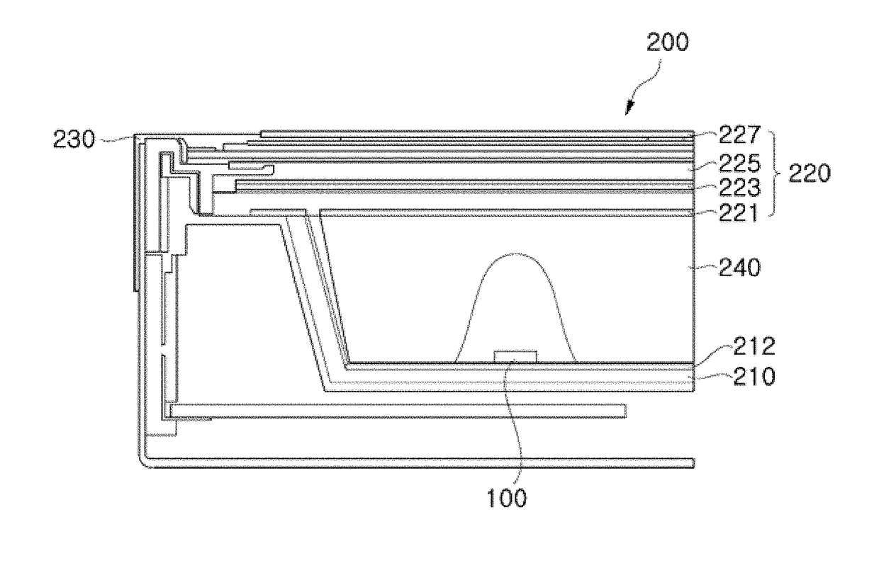
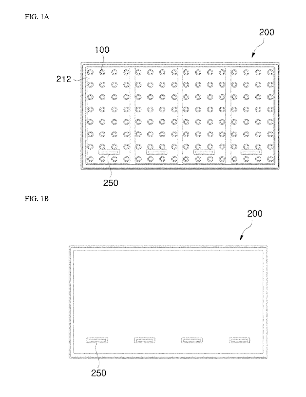
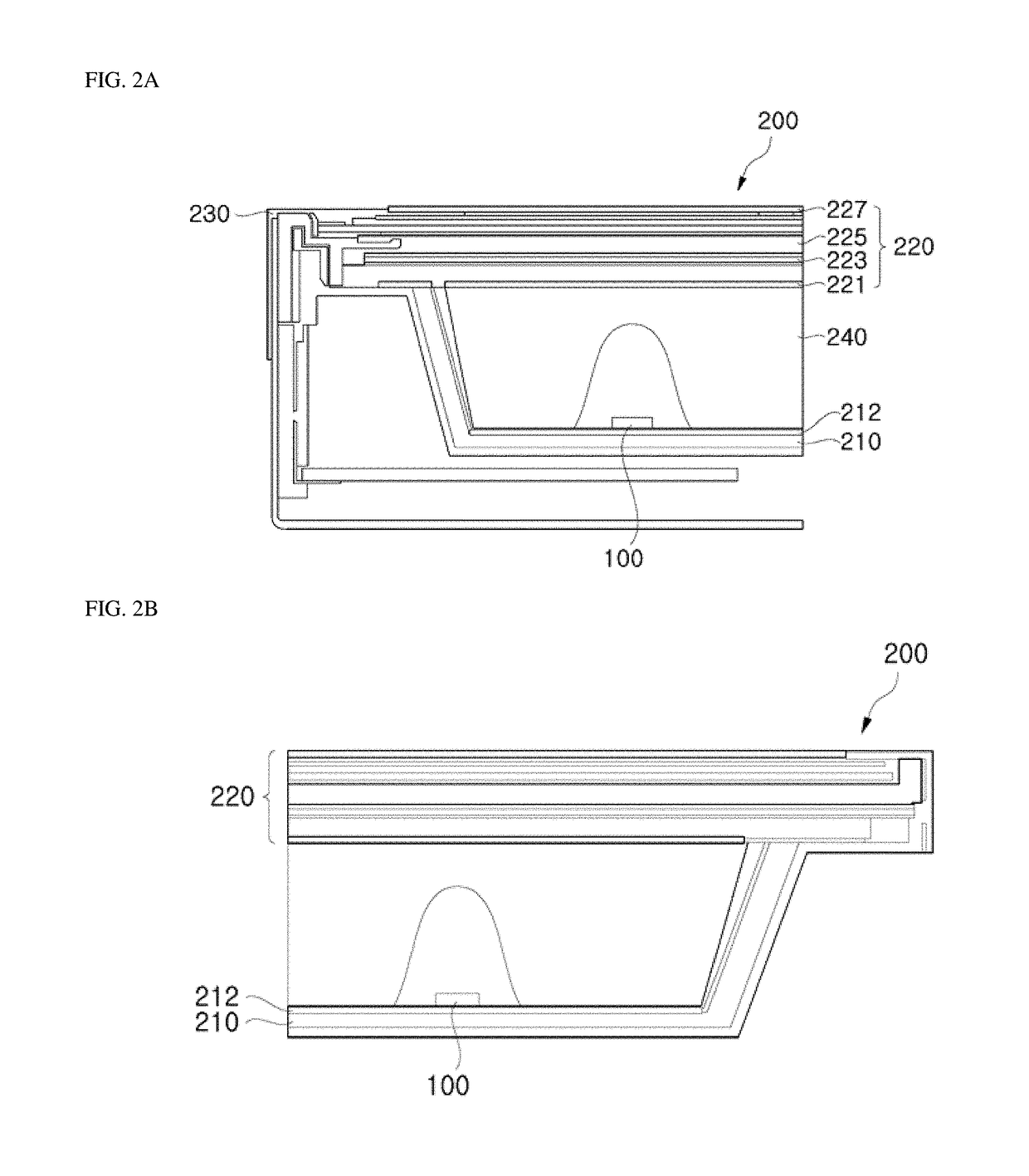
A display apparatus and a backlight unit thereof. The display apparatus includes: a frame; a plurality of light emitting diodes regularly arranged on the frame; an optical part disposed above the plurality of light emitting diodes and including a display panel and at least one of a phosphor sheet and an optical sheet; and a light guide plate disposed between the frame and the optical part to cover the plurality of light emitting diodes, wherein the light guide plate is formed with light source grooves placed corresponding to locations of the plurality of light emitting diodes, respectively, such that light emitted from each of the light emitting diodes enters the corresponding light source groove to spread light in a lateral direction when the light enters the light guide plate, thereby enabling use of a direct type backlight unit without a separate lens.

Description

CROSS-REFERENCE TO RELATED APPLICATIONS[0001]This application claims priority from and the benefit of U.S. Provisional Patent Application No. 62 / 421,454, filed on Nov. 14, 2016; U.S. Provisional Patent Application No. 62 / 422,157, filed on Nov. 15, 2016; and U.S. Provisional Patent Application No. 62 / 436,553, filed on Dec. 20, 2016, which are each hereby incorporated by reference for all purposes as if fully set forth herein.BACKGROUNDField[0002]Exemplary embodiments of the inventive concepts relate to a display apparatus and a backlight unit thereof, and more particularly, to a display apparatus emitting light through a direct type backlight and a backlight unit thereof.Discussion of the Background[0003]Recently, there is increasing demand for making a display apparatus as thin as possible. Accordingly, for a liquid crystal display (LCD), an edge type backlight unit, including a light source disposed at one side thereof, is generally used.[0004]However, a liquid crystal display incl...

Claims


Application Information

Patent Timeline
IPC IPC(8): G02F1/1335F21V8/00
CPCG02F1/133606G02F1/133603G02F1/133608G02B6/0021G02B6/0036G02F1/133605G02F2001/133614H01L25/0756H01L33/62H01L33/60H01L33/54H01L33/502H01L2933/0091G02F1/133611H01L25/0753G02F2201/086G02B6/0068H01L33/507G02B6/0043G02F2201/307H01L33/46G02F1/133614G02F1/133607G02B6/0016G02B6/003G02B6/0055G02B6/0073G02B6/0083
Inventor KIM, EUN JU
Owner SEOUL SEMICONDUCTOR
Learn More