Method and user equipment for allocating uplink power in a mobile communication system

a mobile communication system and power distribution technology, applied in the direction of power management, electrical equipment, wireless communication, etc., can solve the problems of power waste, ue may unnecessarily scale the power, and the current method of adjusting the uplink power may not work normally, so as to improve the efficiency of uplink scheduling and power waste.

Active Publication Date: 2018-05-17
SAMSUNG ELECTRONICS CO LTD
View PDF10 Cites 54 Cited by
  • Summary
  • Abstract
  • Description
  • Claims
  • Application Information

AI Technical Summary

Benefits of technology

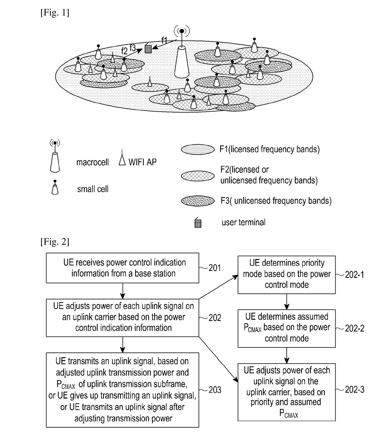
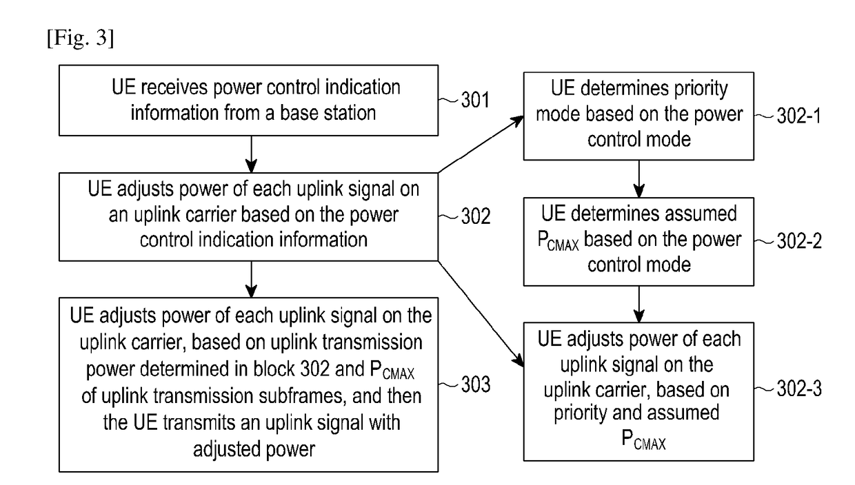
[0042]Based on the foregoing technical solutions, it can be seen that, the UE in the present disclosure determines the priority of each scheduled uplink transmission carrier, and the assumed maximum uplink transmission power PCMAX of a corresponding uplink subframe. The UE determines the actual transmission power of each uplink transmission carrier, based on the priority and assumed PCMAX. And then, the UE transmits uplink signals. In foregoing modes, by using the priority and assumed PCMAX, power may be allocated for multiple different uplink transmission carriers orderly. Subsequently, power waste occurred in the following scene may be reduced. Scheduled uplink signals cannot be transmitted on a corresponding carrier due to a busy channel Thus, uplink scheduling efficiency of the UE will be improved, and the whole network efficiency will also be enhanced.

Problems solved by technology

Due to uncertainty of uplink transmission of carriers in the unlicensed frequency bands of the LAA system, the base station may not effectively configure uplink power for a UE, and the UE may not timely adjust the uplink power or UE may unnecessarily scale the power of some UL carriers due to assumed power limitation.
Subsequently, current method for adjusting the uplink power may not work normally.
Thus, for a UE working in the carrier aggregation mode, which is configured with at least one carrier in the unlicensed frequency bands, how to allocate uplink power is an urgent problem to be solved.

Method used


Image

  • Method and user equipment for allocating uplink power in a mobile communication system
  • Method and user equipment for allocating uplink power in a mobile communication system
  • Method and user equipment for allocating uplink power in a mobile communication system

Examples


embodiment 1

[0057]In the embodiment, a specific mode for determining the actual transmission power of each uplink signal on an uplink carrier and transmitting uplink signals is as follows. Adjust transmission power of each uplink signal on the uplink carrier, based on the priority and assumed maximum uplink transmission power. It should be noted that, although maximum uplink transmission power is represented with total configured maximum output power PCMAX in several Embodiments of the present disclosure, the maximum uplink transmission power in the present disclosure actually includes PCMAX, and / or configured maximum output power for serving cell c PCMAX,c. Transmit an uplink signal corresponding to each uplink carrier, or give up transmitting the uplink signal, based on the adjusted uplink transmission power of each uplink carrier and a set PCMAX and / or PCMAX,c when actually transmitting an uplink subframe.

[0058]Preferably, the assumed PCMAX and / or PCMAX,c should be the same with set PCMAX an...

embodiment 2

[0190]In the embodiment, there are three modes to determine the actual transmission power of each uplink signal on an uplink carrier. A first mode is to adjust the power of each uplink signal on the uplink carrier, directly based on the priority, the assumed PCMAX and / or PCMAX,c and the actual PCMAX and / or PCMAX,c of an uplink subframe determined in real time. A second mode is to adjust the transmission power of each uplink signal on the uplink carrier, based on the priority and the assumed PCMAX and / or PCMAX,c. Perform a second-time adjustment on uplink transmission power of each uplink signal on the uplink carrier, based on the adjusted uplink transmission power of each uplink carrier and the actual PCMAX and / or PCMAX,c of uplink subframe determined in real time. Transmit an uplink signal based on a result obtained after the second-time adjustment. A third mode is to adjust the power of each uplink signal on the uplink carrier, directly based on the priority and the actual PCMAX a...

embodiment 3

[0231]The embodiment describes a power control method assisted by a UE's report, which includes the following blocks.

[0232]In block 401, a UE reports a processing capability of power adjustment.

[0233]The UE may report the processing capability of power adjustment by using UE capability parameters. 1 bit may be used, e.g., 0 / 1 state may indicate stronger or weaker capability. Alternatively, more bits may be used, so as to display more detailed processing capabilities.

[0234]In block 402: the UE receives a power control mode, which is configured by a base station based on the processing capability reported by the UE.

[0235]The base station may configure the power control mode for the UE explicitly. For example, high-level signaling configures power control indication information. The base station utilizes the power control indication information to indicate the power control mode (same as Embodiment 1). The base station may also configure the power control mode for the UE implicitly. Fo...


PUM


Abstract

The present disclosure relates to a pre-5th-Generation (5G) or 5G communication system to be provided for supporting higher data rates Beyond 4th-Generation (4G) communication system such as Long Term Evolution (LTE). The present disclosure provides a power allocating method. A User Equipment (UE) receives power control indication information from a control node, obtains a power control mode, and/or, uplink transmission power configuration information. The UE allocates power for each uplink carrier, based on the power control mode, and/or, the uplink transmission power configuration information. By applying the present disclosure, power waste generated in the following scene may be reduced. A scheduled uplink signal cannot be transmitted in a corresponding carrier due to a busy channel. Subsequently, uplink scheduling efficiency of the UE may be improved, and the whole network efficiency may also be enhanced.

Description

CROSS-REFERENCE TO RELATED APPLICATION(S)[0001]This application is a National Phase Entry of PCT International Application No. PCT / KR2016 / 005095, which was filed on May 13, 2016, entitled “METHOD AND USER EQUIPMENT FOR ALLOCATING UPLINK POWER IN A MOBILE COMMUNICATION SYSTEM”, and claims priority to Chinese Patent Application No. 201510250520.2, which was filed on May 15, 2015, the entire contents of which are incorporated herein by reference.TECHNICAL FIELD[0002]The present disclosure relates to a method for allocating uplink power and a corresponding user equipment (UE) in a mobile communication system.BACKGROUND ART[0003]To meet the demand for wireless data traffic having increased since deployment of 4G (4th-Generation) communication systems, efforts have been made to develop an improved 5G (5th-Generation) or pre-5G communication system. Therefore, the 5G or pre-5G communication system is also called a ‘beyond 4G network’ or a ‘post LTE system’.[0004]The 5G communication system...

Claims


Application Information

Patent Timeline
Patent Type & Authority Applications(United States)
IPC IPC(8): H04W52/14H04W52/28H04W72/10H04W72/04
CPCH04W52/146H04W52/281H04W72/10H04W72/0473H04W72/0413H04W52/14H04W52/28H04W52/34H04W52/367H04W72/569H04W72/56H04W72/21
Inventor WANG, YIZHANG, SHICHANGLI, YINGYANGFU, JINGXING
Owner SAMSUNG ELECTRONICS CO LTD
Why Eureka
Try Eureka