Apparatus and methods for tissue reduction

a tissue and apparatus technology, applied in the field of apparatus and methods for tissue reduction, can solve the problems of affecting social and business activities, affecting a quality of life, and often swelling of tissue, and achieve the effect of precise positioning and control of the coring process

Active Publication Date: 2018-05-24
CORIT LLC
View PDF38 Cites 13 Cited by
  • Summary
  • Abstract
  • Description
  • Claims
  • Application Information

AI Technical Summary

Benefits of technology

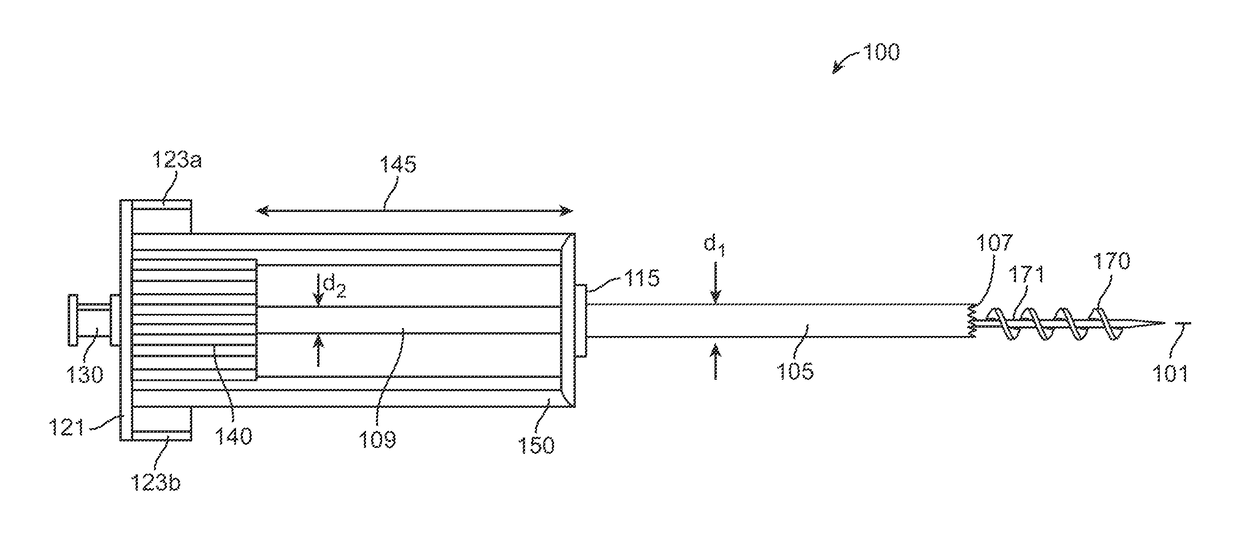
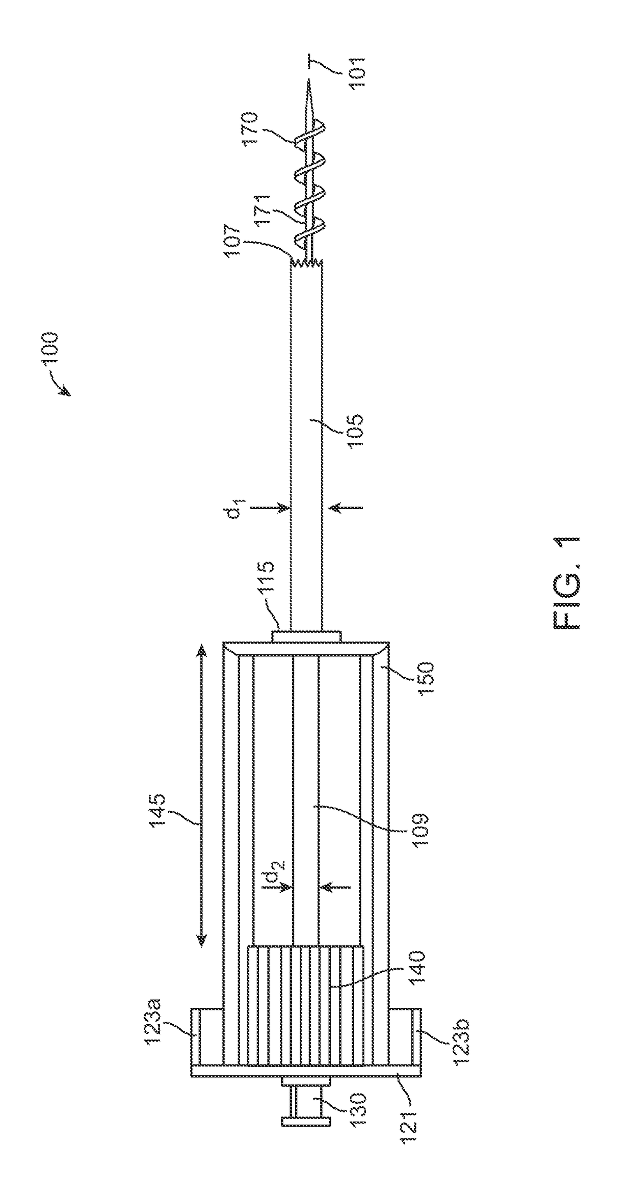
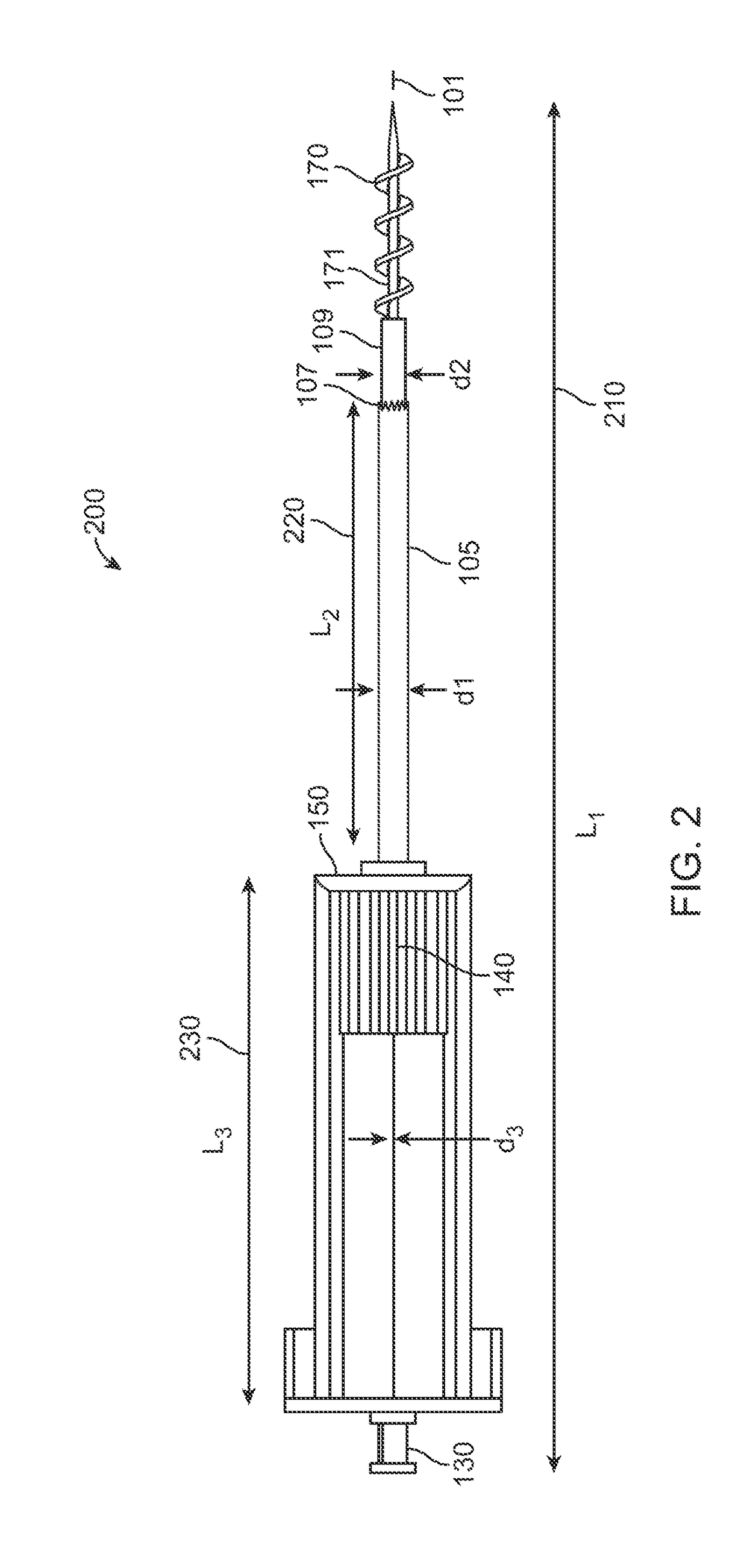
[0009]The present disclosure provides for a device to submucosally resect tissue. The device may generally include a guiding needle(s), a spiraling needle, and a coring blade that allows for precise positioning and control of the coring process, and clamping elements that secure the turbinate tissue during the coring process. Furthermore, by one embodiment of the present disclosure, the device is a non-powered instrument that provides tactile feedback from the tissue being resected, a feature that is often absent with powered medical instrumentation.
[0010]In one embodiment, the location of a desired operation (e.g., position on the inferior turbinate from where tissue is to be resected) is initially directed with the use of the guiding needle. The spiraling needle is subsequently inserted and provides a template to direct and control the coring blade, which enables resection of a chunk of the turbinate tissue in a controlled manner.
[0021]A coring needle having a distal cutting edge may be slidably positioned along the device and positioned proximally of the clamp members. During use, the coring needle may be positioned proximally of the clamp members as the clamp members are advanced into, e.g., the nasal cavity and directly into the turbinate tissue region of interest for treatment. The clamp members may pierce into the tissue and once suitably advanced a sufficient distance, a position of the clamp members may be maintained relative to the tissue while the coring needle may be advanced distally over the clamp members by pushing the coring needle handle. As the cutting edge is advanced distally, the coring needle (or a separate elongate element) may contact against and urge the clamp members towards one another due to their radial curvature or angle so that the tissue positioned within the clamping region between the clamp members are squeezed or secured to provide better capture or purchase of the tissue as well as providing a counter force as the cutting edge cuts the surrounding tissue. As described herein, the curvature or angle along the clamp members may be embodied in any number of different configurations and thus the curvature or angle may be located along any portion of the clamp members so long as the clamp members are urged towards one another as the coring needle (or separate elongate element) is advanced over the clamp members.
[0029]Another variation of a coring needle which may be advanced within or externally of any of the clamping assemblies described herein, as practicable, may include a coring needle having an integrated blade. The coring needle body may define a lumen within and may also have a reconfigurable blade along a side portion of the needle body. The blade may be defined by a slit or groove which extends at with a curvature or at an angle relative to the needle body. The needle body may be advanced within the tissue either within a lumen of a clamping assembly or externally of a clamping assembly and as the needle body is advanced distally, the blade may maintain its closed configuration to present a relatively smooth surface to the tissue. However, when the needle body is retracted proximally within the tissue, the tip of the blade may gain purchase into the tissue and retract further within the lumen and into its extended configuration into the tissue as the needle body is further pulled proximally. Yet another variation of a coring needle may also include a coring needle having an integrated blade shaped in a leaf-like configuration.

Problems solved by technology

Such a condition can interfere with social and business activities and moreover negatively affect a quality of life.
The soft tissue often swells and shrinks, thereby contributing to obstruction of the nasal airway.
However, this technique often results in deleterious physiological effects including dry nose, excessive crusting, and scarring.
However, a drawback associated with the microdebrider and electronic ablation devices is that the instruments are powered, and thus require additional generation and control equipment, which increases the cost of procedure, and limits the availability of such devices only in operation theaters.
Thus, to resect a large amount of the inferior turbinate requires a significant period of time to sequentially remove incremental small pieces of the turbinate tissue, which prolongs the procedure and causes discomfort to conscious patients and poses stringent, accurate device positioning requirements on the surgeons.
Furthermore, microdebrider and electronic ablation devices have a substantial weight and incur vibrations (due to their powered nature) while in operation.
Such vibrations hinder the tactile feedback provided by the devices to the surgeons.

Method used


Image

  • Apparatus and methods for tissue reduction
  • Apparatus and methods for tissue reduction
  • Apparatus and methods for tissue reduction

Examples


embodiment 1400

[0117]Another embodiment is shown in the perspective views of FIGS. 14A to 14E which illustrates an embodiment 1400 similarly having an anchoring needle base 1306 with multiple anchoring needles 1308 and the coring needle 1302. This embodiment may further incorporate an additional spiraling needle body 1402 (e.g., Trim Helix) having a helically shaped blade 1404 (or any of the blade configurations described herein) to trim the cored turbinate tissue after coring. The spiraling needle body 1402 may also be advanced into the tissue to pre-trim and capture the tissue (as described herein) prior to introduction of the coring needle. As shown in FIG. 14A, the spiraling needle body 1402 may be advanced through the coring needle 1302 and between the anchoring needles 1308 before or after the coring needle 1302 has been advanced, as shown in FIG. 14C. FIG. 14D shows a detail perspective view of the blade 1404 extended distally beyond the piercing tips 1308 and cutting edge 1304 of coring ne...

embodiment 1500

[0118]FIGS. 15A to 15F illustrate yet another embodiment 1500 in which a needle base 1502 may incorporate one or more blades 1506 which are configured as individual cutting elements having piercing tips 1504, as shown in FIG. 15C and detail view of FIG. 15B. A sheath 1508 may also be incorporated to slidingly translate over the needle base 1502 and one or more blades 1506, as illustrated in FIG. 15A. Additionally, a coring needle 1302 may also be introduced through the needle base 1502 for coring the tissue, as shown in FIG. 15D and detail view of FIG. 15E. In use, the anchoring blades 1506 may be initially covered by and circumferentially supported through sheath 1508 during initial introduction into proximity of the tissue to be resected. The anchoring blades 1506 may be advanced into the turbinate tissue while cutting the tissue via the blades and the coring needle 1302 may then be introduced through the needle base 1502 and blades 1506 to core the tissue. FIG. 15F illustrates a ...

embodiment 1800

[0123]In yet another embodiment, instead of using piercing needles to anchor the tissue region, clamping mechanisms may be used to engage and hold an exterior surface of the tissue region. FIGS. 18A to 18F illustrate an embodiment 1800 which incorporates a sliding clamp mechanism 1802 and a distal clamp mechanism 1806 that may be used to engage and hold the tissue of the anterior surface of the turbinate, e.g., prior to introduction of the coring needle. The distal clamp 1806 may be formed as a shoulder or surface which extends radially from a distal end of a translatable tubular member 1804 while the sliding clamp mechanism 1802 may be formed as a tubular member which defines projections, notched features, or any other mechanism configured to engage tissue, as shown in FIGS. 18A and 18B. The sliding clamp mechanism 1802 may be translatably positioned exterior to the translatable tubular member 1804 so that when the clamp mechanism 1802 and distal clamp 1806 are translated towards o...


PUM


Abstract

Apparatus and methods for tissue reduction are described where one embodiment of the tissue resection device may generally comprise an external clamping mechanism having at least two distally extending members shaped with an atraumatic distal end and defining a confined region between the distally extending members sized to receive a tissue region therebetween. Additionally, an elongate coring needle defining a lumen and having a proximal end attached to a handle and a distal end which defines a cutting mechanism may also be included, wherein the coring needle is translatable adjacent and / or relative to the external or internal clamping mechanism defined by the confined region.

Description

CROSS-REFERENCE TO RELATED APPLICATIONS[0001]This application claims the benefit of priority to U.S. Provisional Application Nos. 62 / 426,053 filed Nov. 23, 2016 and 62 / 435,943 filed Dec. 19, 2016, each of which is incorporated herein by reference in its entirety.FIELD OF THE INVENTION[0002]The present disclosure relates generally to an apparatus for performing coring (e.g., resection) of tissue such as the inferior turbinate tissue. Specifically, the disclosure is related to a medical apparatus and methods for coring tissues such as the turbinate tissues.BACKGROUND OF THE INVENTION[0003]The background description provided herein is for the purpose of generally presenting the context of the disclosure. Work of the presently named inventors, to the extent the work is described in this background section, as well as aspects of the description that may not otherwise qualify as prior art at the time of filing, are neither expressly nor impliedly admitted as prior art against the present ...

Claims


Application Information

Patent Timeline
Patent Type & Authority Applications(United States)
IPC IPC(8): A61B17/3205A61B1/313A61B17/16A61B17/295
CPCA61B17/32053A61B1/313A61B17/1615A61B17/295A61B17/1637A61B2017/246A61B2017/320052A61B2017/320064A61B2090/036A61B2090/062A61B17/24A61B17/30A61B2017/3488A61B2017/00199A61B2017/00221A61B2017/00734A61B2090/034A61B17/1688
Inventor SAIDI, IYADLOPER, CAMERONHUCK, CHARLES M.MAZURICK, RYANWHITCRAFT, JONATHAN
Owner CORIT LLC
Why Eureka
Try Eureka