Method of driving display device and method of producing display device
a display device and display technology, applied in the direction of identification means, instruments, optics, etc., can solve the problems of reducing the display quality of the display device, light leakage, etc., and achieve the effect of reducing the production cos
- Summary
- Abstract
- Description
- Claims
- Application Information
AI Technical Summary
Benefits of technology
Problems solved by technology
Method used
Image
Examples
first embodiment
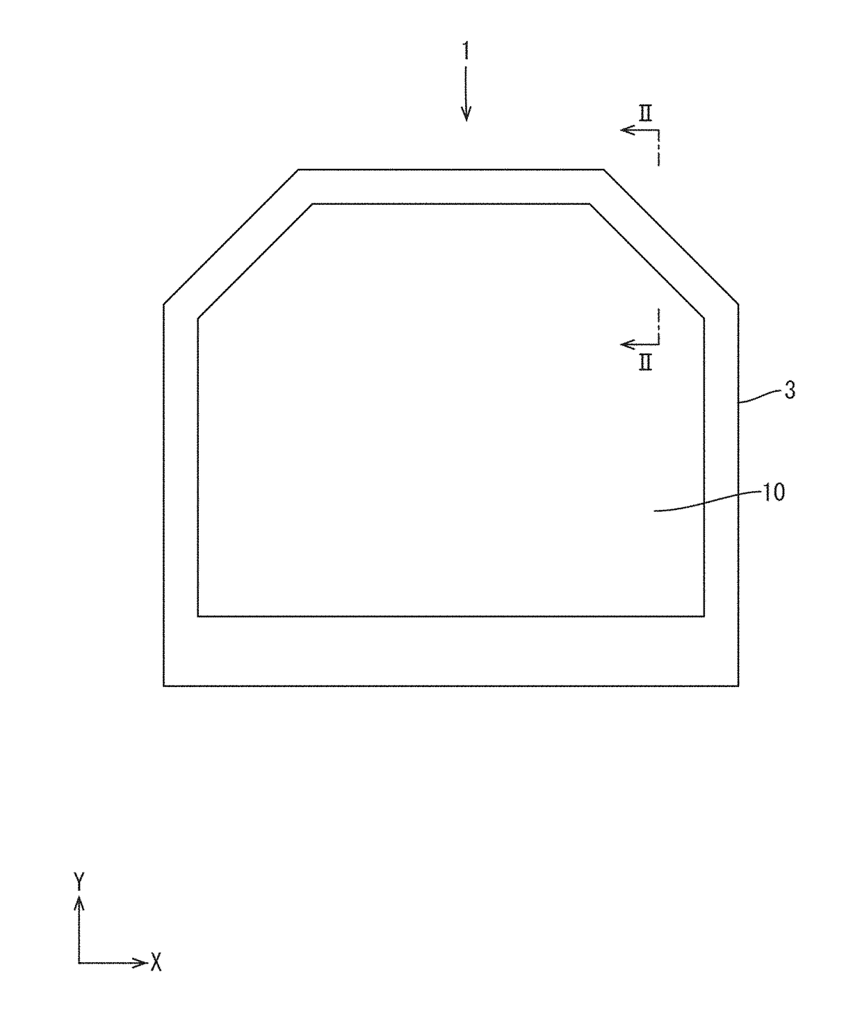
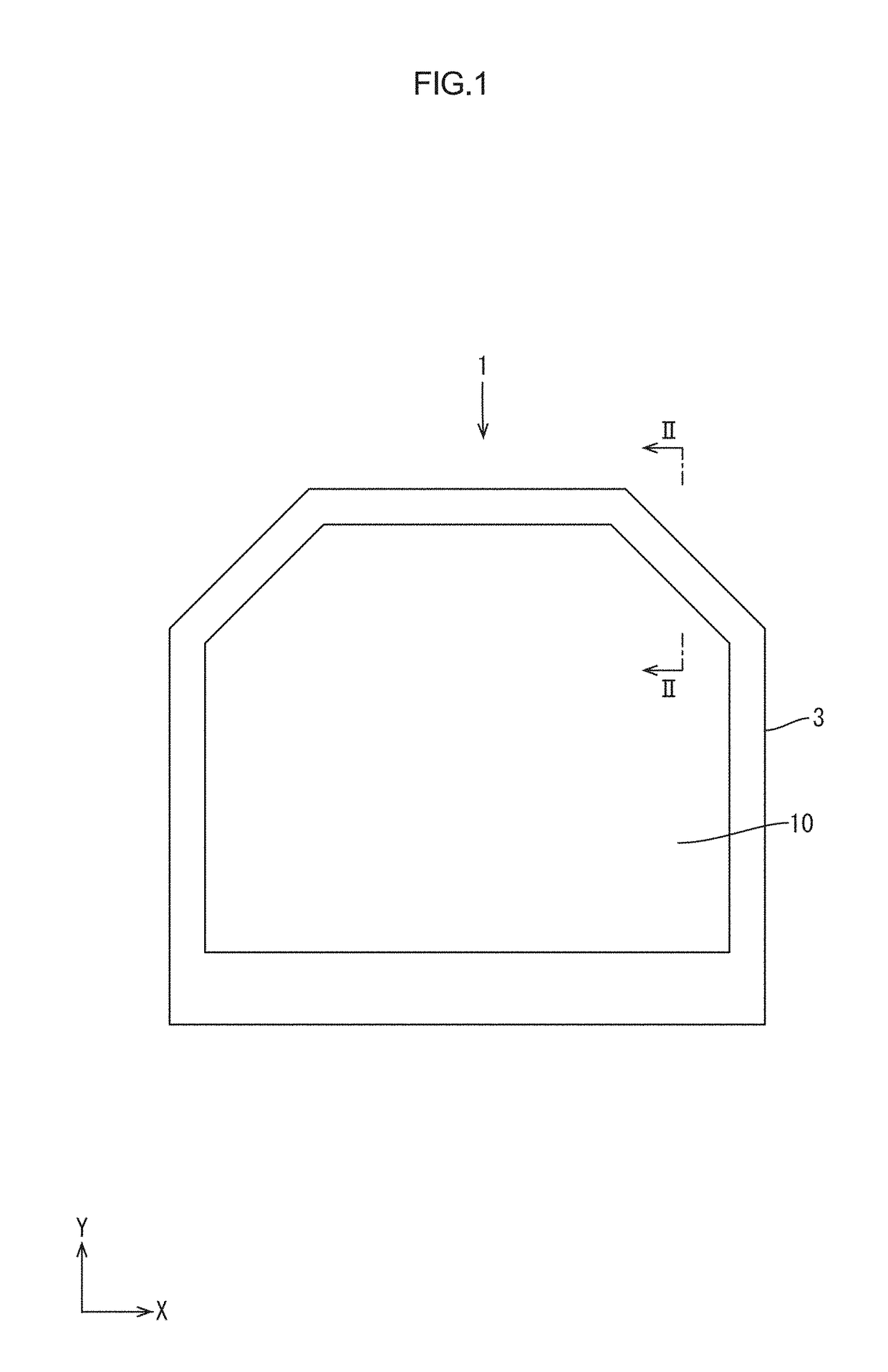
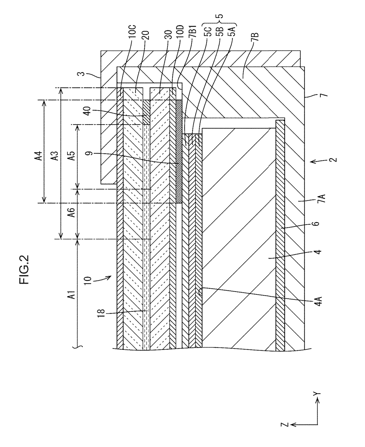
[0053]The first embodiment of the present invention will be described with reference to FIGS. 1 to 15. In this section, a liquid crystal display device 1 including a liquid crystal panel 10a as illustrated in FIG. 1 will be described. X-axes, Y-axes, and Z-axes may be provided in the drawings. The axes in each drawing correspond to the respective axes in other drawings to indicate the respective directions. An upper side in each drawing illustrating the cross-sectional view corresponds to an upper side (a front side) of the liquid crystal display device 1 (or the liquid crystal panel 10).
[0054]The liquid crystal display device described in this section has a hexagonal outer shape with inequality angles in a plan view, which is not a regular rectangular or square shape. Specifically, as illustrated in FIG. 1, the liquid crystal display device 1 has a hexagonal shape with two corners on the lower side in FIG. 1 at an angle of about 90 degrees and four corners at an angle of about 135 ...
second embodiment
[0095]A second embodiment of the present invention will be described with reference to FIGS. 16 to 19. The second embodiment includes a liquid crystal panel 110 included in a liquid crystal display device having configurations, some of which are different from the first embodiment. Furthermore, some processes of a method of producing the liquid crystal display device are different from the first embodiment. Other configurations of the liquid crystal display device and the other processes of the method of producing the liquid crystal display device are similar to those of the first embodiment and thus will not be described.
[0096]As illustrated in FIG. 16, the liquid crystal panel 110 in the liquid crystal display device according to this embodiment includes a color filter board 120. The color filters 22 and the light blocking section 23 are not formed in an area of the color filter board 120 overlapping the sealant 40 in the thickness direction of the liquid crystal panel 110. As ill...
third embodiment
[0102]A third embodiment will be described with reference to FIGS. 20 to 23. The third embodiment includes a liquid crystal panel 210 included in a liquid crystal display device having configurations, some of which are different from the first embodiment. Furthermore, some processes of a method of producing the liquid crystal display device are different from the first embodiment. Other configurations of the liquid crystal display device and the other processes of the method of producing the liquid crystal display device are similar to those of the first embodiment and thus will not be described.
[0103]In the liquid crystal panel 210 in the liquid crystal display device, as illustrated in FIG. 19, the light blocking section 23 is formed in an entire area of a section of a color filter board 220 closer to the first glass substrate 20A and the color filters 22 are formed in a section of the color filter board 220 closer to the liquid crystal layer 18 in a large section of the frame are...
PUM
| Property | Measurement | Unit |
|---|---|---|
| colors | aaaaa | aaaaa |
| thickness | aaaaa | aaaaa |
| voltage | aaaaa | aaaaa |
Abstract
Description
Claims
Application Information
 - R&D
- Intellectual Property
- Life Sciences
- Materials
- Tech Scout
- Unparalleled Data Quality
- Higher Quality Content
- 60% Fewer Hallucinations
Browse by: Latest US Patents, China's latest patents, Technical Efficacy Thesaurus, Application Domain, Technology Topic, Popular Technical Reports.
© 2025 PatSnap. All rights reserved.Legal|Privacy policy|Modern Slavery Act Transparency Statement|Sitemap|About US| Contact US: help@patsnap.com


