RF Power Detector Circuits

a detector circuit and radio frequency technology, applied in the field of circuits, can solve the problems of reducing the transmission efficiency, affecting the accuracy of measurements, and distortion of signals to be measured,

Active Publication Date: 2018-05-24
INFINEON TECH AG
View PDF2 Cites 4 Cited by
  • Summary
  • Abstract
  • Description
  • Claims
  • Application Information

AI Technical Summary

Benefits of technology

[0004]In accordance with an embodiment, a radio frequency (RF) power detector includes a first circuit having a first rectifying diode with a first terminal coupled to a first power supply voltage node. The first circuit also includes an input terminal coupled to a second terminal of the first rectifying diode, a first transistor having a first collector coupled to the second terminal of the first rectifying diode and a first emitte

Problems solved by technology

For example, when RF power detector is inserted or coupled to a certain location of a RF circuit to measure the power of the RF signal, impedance mismatch may cause signal reflections that reduces the transmission e

Method used


Image

  • RF Power Detector Circuits
  • RF Power Detector Circuits
  • RF Power Detector Circuits

Examples


Embodiment Construction

[0025]The making and using of the presently preferred embodiments are discussed in detail below. It should be appreciated, however, that the present invention provides many applicable inventive concepts that can be embodied in a wide variety of specific contexts. The specific embodiments discussed are merely illustrative of specific ways to make and use the invention, and do not limit the scope of the invention.

[0026]The present invention will be described with respect to preferred embodiments in a specific context, systems and methods for RF power detector circuits.

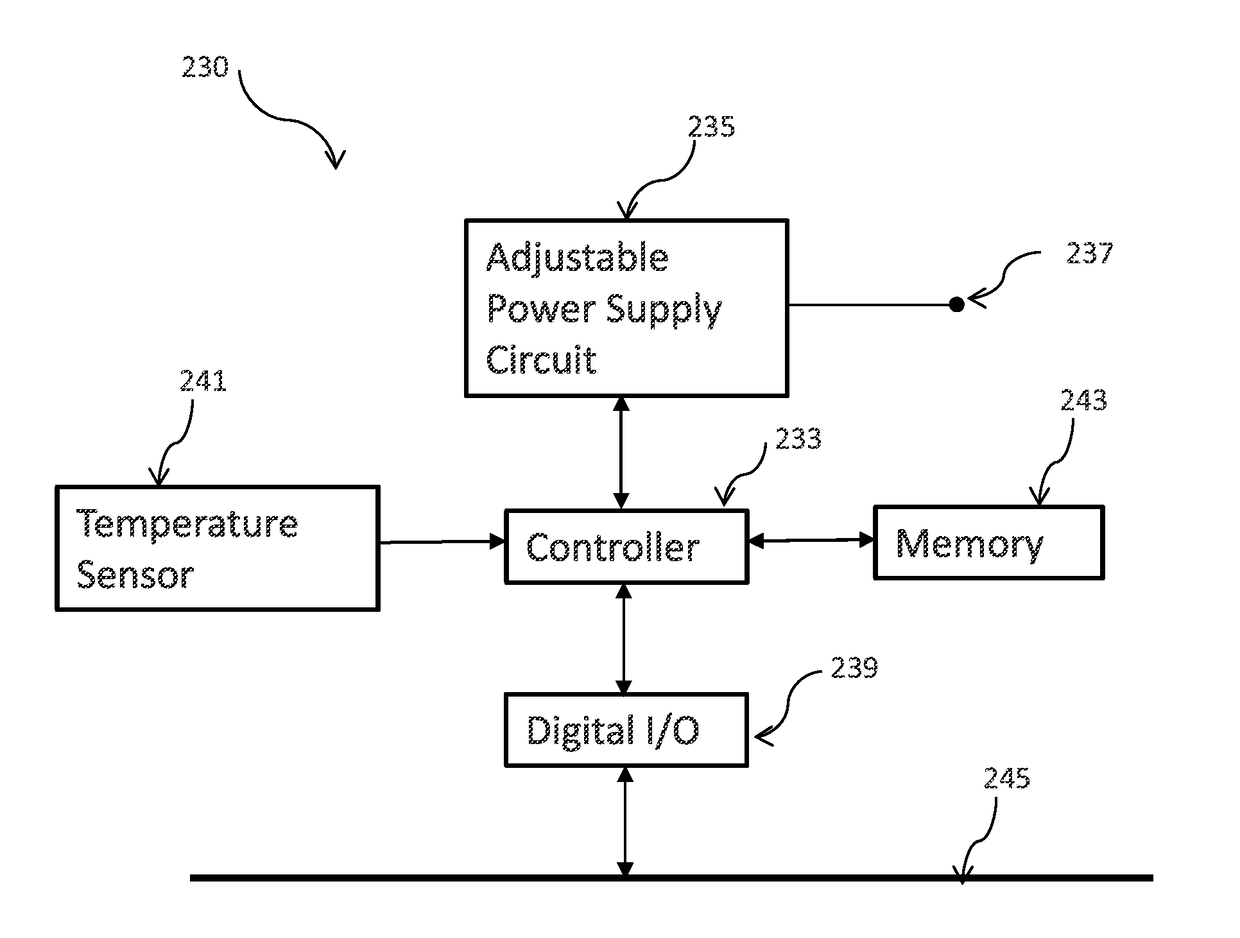
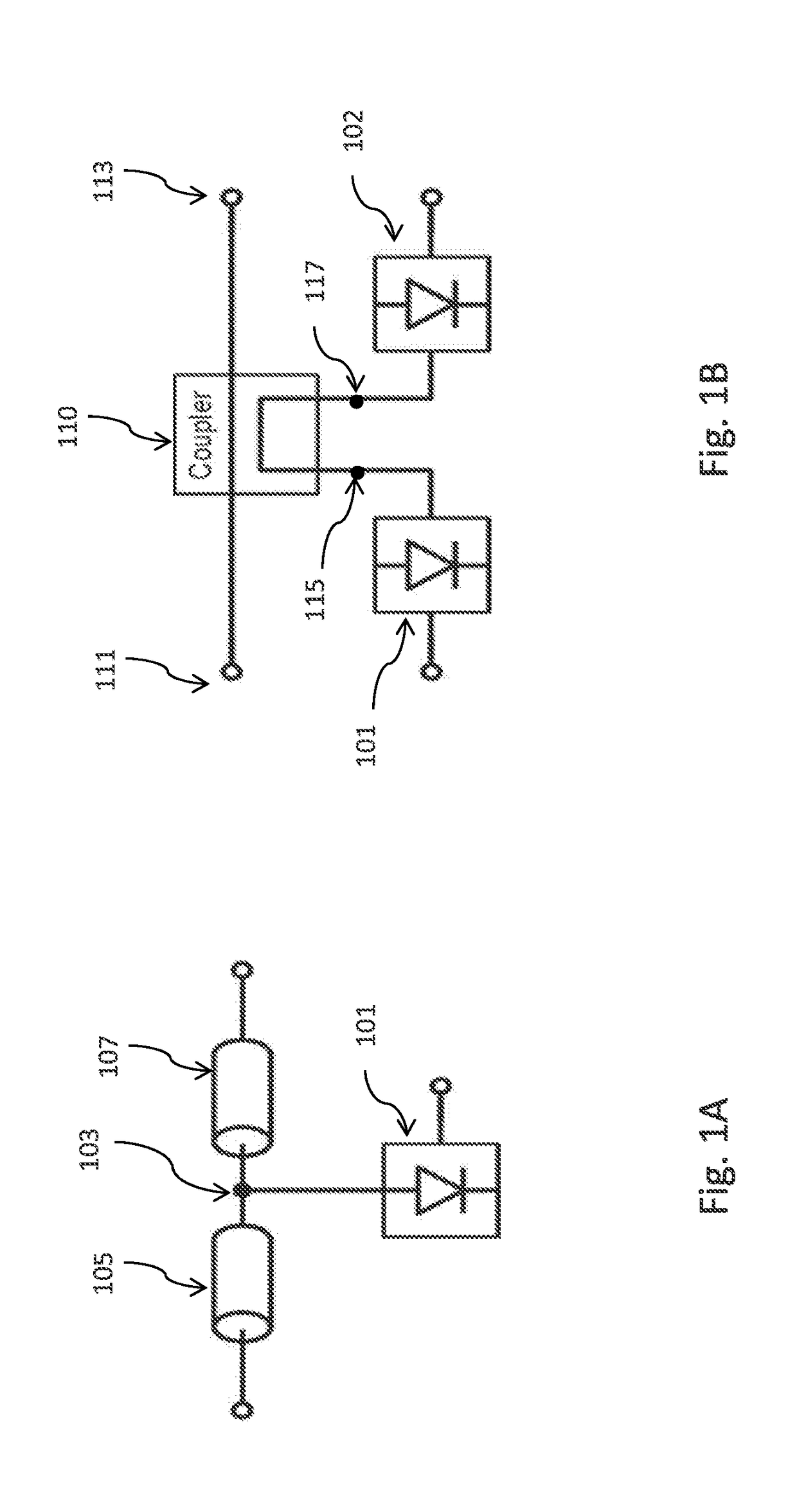
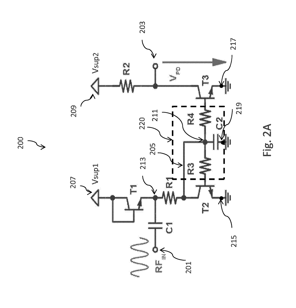
[0027]In accordance with an embodiment of the present disclosure, an RF power detector includes a diode coupled to an input of a current mirror via a resistor. The resistor provides broadband matching over a wide range of frequencies. For robust operation against temperature drift, a power supply circuit may be used to adjust an input voltage of the RF power detector circuit in accordance with the temperature, in some em...


PUM


Abstract

A radio frequency (RF) power detector includes a first circuit having a first rectifying diode with a first terminal coupled to a first power supply voltage node. The first circuit also includes an input terminal coupled to a second terminal of the first rectifying diode, a first transistor having a first collector coupled to the second terminal of the first rectifying diode and a first emitter coupled to a reference voltage node, and a second transistor having a second emitter coupled to the reference voltage node and a second collector coupled to a second power supply voltage node. The first circuit further includes a low-pass filter network coupled between a first base of the first collector and a second base of the second transistor, and a first output terminal coupled to the second collector of the second transistor.

Description

TECHNICAL FIELD[0001]The present disclosure relates generally to circuits, in particular to systems and methods for radio frequency (RF) power detector circuits.BACKGROUND[0002]RF power detectors circuits (also referred to as RF power detectors) are widely used in various applications involving RF signals. For example, in a RF transmitter, RF power detectors may be used to monitor the power of the RF output signal. Measurement from RF power detectors may be used in a feedback control loop to generate RF output signal at predetermined power levels. In an antenna array, measurements from RF power detectors at all of the antenna elements may be used to detect antenna mismatch, as another example. In addition, RF power detectors may also be used as part of a calibration circuit for calibration, or in production testing circuit to determine whether a device is defective.[0003]Challenges abound in RF power detector circuit design. For example, when RF power detector is inserted or coupled...

Claims


Application Information

Patent Timeline
IPC IPC(8): H03F1/30H03F3/195H03F1/02G01R21/10
CPCH03F1/302H03F3/195H03F1/0222H03F2200/451H03F2200/165H03F2200/555H03F2200/387G01R21/10H03F1/0266H03F2200/105H03F2200/18G01R21/01
Inventor SCHLEICHER, BERND
Owner INFINEON TECH AG
Why Eureka
Try Eureka