Aerosol-generating system with adjustable pump flow rate

a technology of pump flow rate and aerosol, which is applied in the direction of inhalators, tobacco, other medical devices, etc., can solve the problem of difficult control of dose delivery

Active Publication Date: 2018-05-31
AKRIA CLIENT SERVICES LLC
View PDF0 Cites 34 Cited by
  • Summary
  • Abstract
  • Description
  • Claims
  • Application Information

AI Technical Summary

Benefits of technology

[0004]In another type of aerosol-generating systems a reservoir, a micropump and a vaporizer may be included. During a puff, a constant stream of e-liquid is actively pumped from the liquid storage portion to the vaporizer. The flow rate of the micropump is kept constant such that an active control of the delivered dose is achieved. In this way a homogenous delivery of nicotine during an inhaling experience is provided.
[0010]In at least one example embodiment, a method of generating an aerosol comprises pumping a liquid aerosol-forming substrate from a liquid storage portion to a vaporizer using a pump, the vaporizer including, a heating element configured to vaporize the liquid aerosol-forming substrate; sensing a puff using a puff sensor, the puff sensor in an airflow path of the aerosol-generating system, the puff sensor configured to sense a puff; and determining, using a controller, a puff intensity by comparing an output from the puff sensor with values stored in a look-up table, the controller configured to adjust a delivery flow rate of the pump and electrical power supplied to the heating element in response to the determined puff intensity.
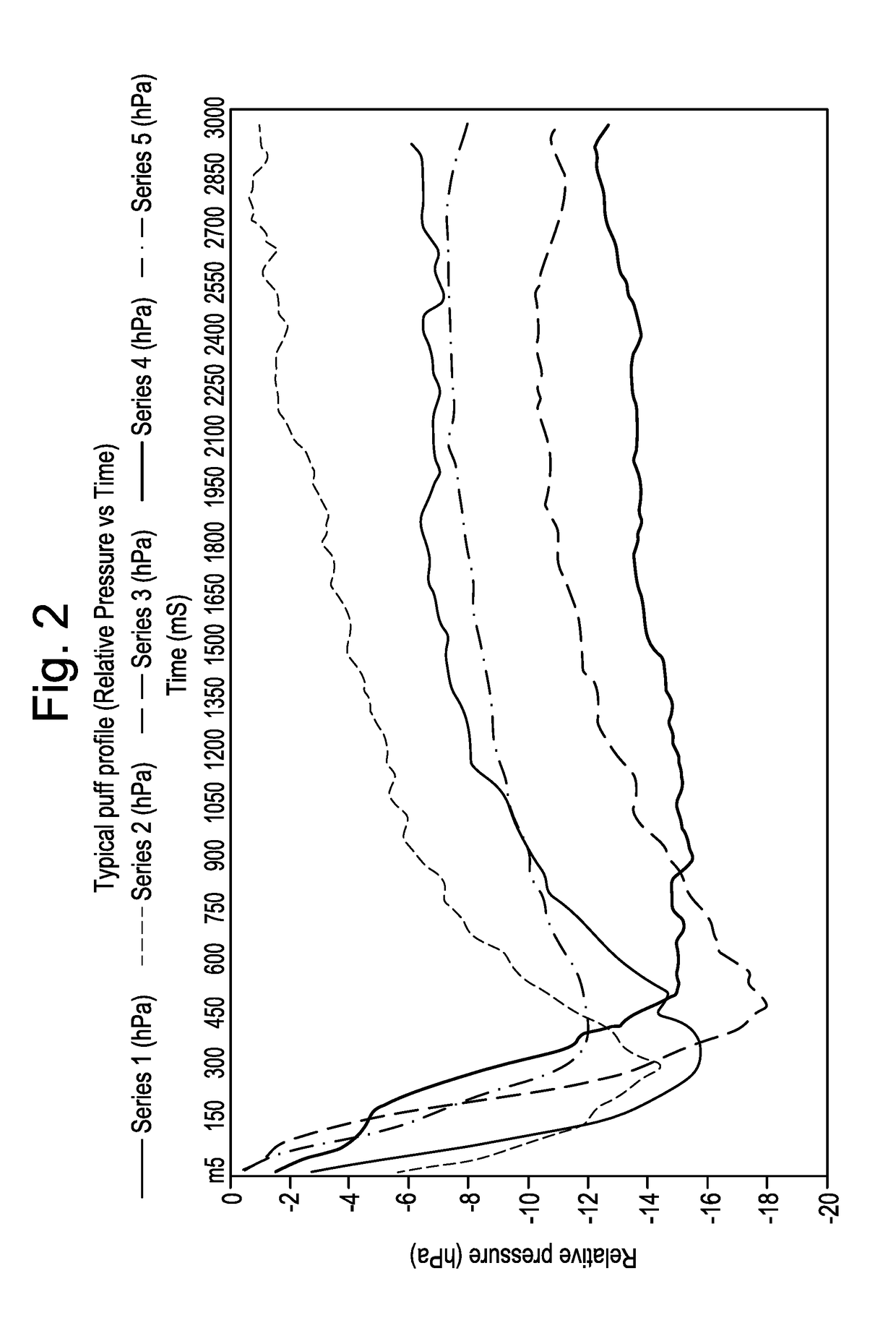
[0038]The sensor may be configured as an airflow sensor and may measure the airflow rate. The airflow rate indicates the amount of air that is drawn through the airflow path of the aerosol-generating system per time by the vaper. Depending upon the detected airflow rate, the puff intensity may be determined. The higher the detected airflow rate is, the higher the determined puff intensity is. The airflow rate may be detected about 0.3 seconds to about 0.6 seconds or about 0.5 seconds after the initiation of the puff. The initiation of the puff may be detected by the airflow sensor when the airflow exceeds a desired (or, alternatively predetermined) threshold. Initiation may also be detected upon a vapor activating a button.
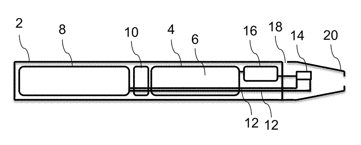
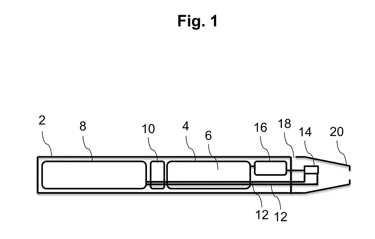
[0007]In at least one example embodiment, an aerosol-generating system comprises a housing including an air inlet and an air outlet, an airflow path defined between the air inlet and the air outlet; vaporizer configured to vaporize an aerosol-forming substrate, the vaporizer including, a heating element; a liquid storage portion configured to contain the aerosol-forming substrate; a pump configured to deliver the aerosol-forming substrate from the liquid storage portion to the vaporizer; a puff sensor in the airflow path, the puff sensor configured to sense a puff, and a controller connected to the puff sensor and to the heating element, the controller configured to determine a puff intensity based on an output from the puff sensor and adjust a delivery flow rate of the pump and the electrical power supplied to the heating element in response to the determined puff intensity.
[0040]The airflow rate or the pressure drop may also be continuously measured by the sensor and the puff intensity may be determined on basis of the highest airflow rate or highest pressure drop value in the course of a puff duration.
[0010]In at least one example embodiment, a method of generating an aerosol comprises pumping a liquid aerosol-forming substrate from a liquid storage portion to a vaporizer using a pump, the vaporizer including, a heating element configured to vaporize the liquid aerosol-forming substrate; sensing a puff using a puff sensor, the puff sensor in an airflow path of the aerosol-generating system, the puff sensor configured to sense a puff; and determining, using a controller, a puff intensity by comparing an output from the puff sensor with values stored in a look-up table, the controller configured to adjust a delivery flow rate of the pump and electrical power supplied to the heating element in response to the determined puff intensity.
[0007]In at least one example embodiment, an aerosol-generating system comprises a housing including an air inlet and an air outlet, an airflow path defined between the air inlet and the air outlet; vaporizer configured to vaporize an aerosol-forming substrate, the vaporizer including, a heating element; a liquid storage portion configured to contain the aerosol-forming substrate; a pump configured to deliver the aerosol-forming substrate from the liquid storage portion to the vaporizer; a puff sensor in the airflow path, the puff sensor configured to sense a puff, and a controller connected to the puff sensor and to the heating element, the controller configured to determine a puff intensity based on an output from the puff sensor and adjust a delivery flow rate of the pump and the electrical power supplied to the heating element in response to the determined puff intensity.
[0010]In at least one example embodiment, a method of generating an aerosol comprises pumping a liquid aerosol-forming substrate from a liquid storage portion to a vaporizer using a pump, the vaporizer including, a heating element configured to vaporize the liquid aerosol-forming substrate; sensing a puff using a puff sensor, the puff sensor in an airflow path of the aerosol-generating system, the puff sensor configured to sense a puff; and determining, using a controller, a puff intensity by comparing an output from the puff sensor with values stored in a look-up table, the controller configured to adjust a delivery flow rate of the pump and electrical power supplied to the heating element in response to the determined puff intensity.
[0010]In at least one example embodiment, a method of generating an aerosol comprises pumping a liquid aerosol-forming substrate from a liquid storage portion to a vaporizer using a pump, the vaporizer including, a heating element configured to vaporize the liquid aerosol-forming substrate; sensing a puff using a puff sensor, the puff sensor in an airflow path of the aerosol-generating system, the puff sensor configured to sense a puff; and determining, using a controller, a puff intensity by comparing an output from the puff sensor with values stored in a look-up table, the controller configured to adjust a delivery flow rate of the pump and electrical power supplied to the heating element in response to the determined puff intensity.
[0045]For determining the puff intensity, predetermined airflow values and / or pressure values may be stored in a look-up table. The controller may be configured to compare the parameter values which are detected by the sensor with the values which are stored in the look-up table to determine the puff intensity. The controller may compare the value, which is detected by the sensor after about 0.3 seconds to about 0.6 seconds or about 0.5 second after the puff initiation with the values stored in the look-up table. The controller may also compare the highest airflow or pressure value, which is detected by the sensor after about 1 second, about 0.7 seconds, or about 0.5 seconds after the initiation of the puff with the values stored in the look-up table. In at least one example embodiment, the controller may compare the highest value, which is measured by the sensor during a puff duration with the values stored in the look-up table.
[0046]The controller may comprise a microprocessor, which may be a programmable microprocessor. The controller may be part of electric circuitry, comprising further electronic components. The controller may be configured to regulate a supply of power to the atomizer. Power may be supplied to the atomizer continuously following activation of the system or may be supplied intermittently, such as on a puff-by-puff basis. The power may be supplied to the atomizer in the form of pulses of electrical current. The pump may be activated until the end of a puff is detected by the sensor.
[0017]In at least one example embodiment, the method may include activating the heating element for an additional predefined period of time about 0.5 seconds after the pump has been deactivated.
[0048]The electrical power supplied to the heating element may be adjusted by means of pulse width modulation. Hereto, a switch may be provided and used for switching between supply and load on and off at a fast rate. During use of pulse width modulation, power loss in the switch is very low. When the switch is off there is little or no current, and when it is on and power is being transferred to the vaporizer, there is almost no voltage drop across the switch. Power loss is thus in both cases very low, increasing the efficiency of the vaporizer.
[0035]According to at least one example embodiment, a method for generating an aerosol in an aerosol-generating system comprises storing a liquid aerosol-forming substrate in a liquid storage portion, delivering via a pump the liquid aerosol-forming substrate from the liquid storage portion to an atomizer, and providing a sensor in an airflow path of the aerosol-generating system. The sensor is configured to sense a puff and / or a puff intensity of the puff. The delivery flow rate of the liquid aerosol-forming substrate to the atomizer is adjusted in response to the sensed puff intensity.
[0035]According to at least one example embodiment, a method for generating an aerosol in an aerosol-generating system comprises storing a liquid aerosol-forming substrate in a liquid storage portion, delivering via a pump the liquid aerosol-forming substrate from the liquid storage portion to an atomizer, and providing a sensor in an airflow path of the aerosol-generating system. The sensor is configured to sense a puff and / or a puff intensity of the puff. The delivery flow rate of the liquid aerosol-forming substrate to the atomizer is adjusted in response to the sensed puff intensity.
[0035]According to at least one example embodiment, a method for generating an aerosol in an aerosol-generating system comprises storing a liquid aerosol-forming substrate in a liquid storage portion, delivering via a pump the liquid aerosol-forming substrate from the liquid storage portion to an atomizer, and providing a sensor in an airflow path of the aerosol-generating system. The sensor is configured to sense a puff and / or a puff intensity of the puff. The delivery flow rate of the liquid aerosol-forming substrate to the atomizer is adjusted in response to the sensed puff intensity.
[0042]The atomizer is configured to atomize the liquid aerosol-forming substrate to form an aerosol, which can subsequently be inhaled by a vaper. The atomizer may comprise a heating element configured to vaporize the liquid aerosol-forming substrate, in which case the atomizer will be denoted as a vaporizer. Generally, the atomizer may be configured as any device which is able to atomize and / or vaporize the liquid aerosol-forming substrate. In at least one example embodiment, the atomizer may comprise a nebulizer or an atomizer nozzle based on the Venturi effect to atomize the liquid aerosol-forming substrate. Thus, the atomization of the liquid aerosol-forming substrate may be realized by a non-thermally aerosolization technique. A mechanically vibrating vaporizer with vibrating elements, vibrating meshes, a piezo-driven nebulizer or surface acoustic wave aerosolization may be used.
[0035]According to at least one example embodiment, a method for generating an aerosol in an aerosol-generating system comprises storing a liquid aerosol-forming substrate in a liquid storage portion, delivering via a pump the liquid aerosol-forming substrate from the liquid storage portion to an atomizer, and providing a sensor in an airflow path of the aerosol-generating system. The sensor is configured to sense a puff and / or a puff intensity of the puff. The delivery flow rate of the liquid aerosol-forming substrate to the atomizer is adjusted in response to the sensed puff intensity.
[0049]According to at least one example embodiment, an aerosol-generating system is provided. The system comprises a housing with an air inlet or semi-open inlet and an air outlet, defining an airflow path there between. The system further comprises an atomizer configured to atomize an aerosol-forming substrate and a pump configured to deliver a liquid aerosol-forming substrate from a liquid storage portion to the atomizer. A puff sensor is provided located in the airflow path. The puff sensor is configured to sense a puff. A controller is configured to determine a puff intensity based on the sensed purr. The delivery flow rate of the liquid aerosol-forming substrate to the atomizer is adjusted in response to the determined puff intensity.
[0053]In at least one example embodiment, the aerosol-generating system further comprises a chamber into which the liquid aerosol-forming substrate is delivered. The heating element is arranged inside the chamber and is downstream of the outlet of the liquid storage portion.
[0042]The atomizer is configured to atomize the liquid aerosol-forming substrate to form an aerosol, which can subsequently be inhaled by a vaper. The atomizer may comprise a heating element configured to vaporize the liquid aerosol-forming substrate, in which case the atomizer will be denoted as a vaporizer. Generally, the atomizer may be configured as any device which is able to atomize and / or vaporize the liquid aerosol-forming substrate. In at least one example embodiment, the atomizer may comprise a nebulizer or an atomizer nozzle based on the Venturi effect to atomize the liquid aerosol-forming substrate. Thus, the atomization of the liquid aerosol-forming substrate may be realized by a non-thermally aerosolization technique. A mechanically vibrating vaporizer with vibrating elements, vibrating meshes, a piezo-driven nebulizer or surface acoustic wave aerosolization may be used.
[0058]The atomizer may comprise a heating coil extending from the tubing segment in longitudinal direction. In at least one example embodiment, the heating coil may be mounted transverse to the tubing segment. The heating coil may overlap with the open end of the tubing segment for up to about 3 millimetres or up to about 1 millimetre. In at least one example embodiment, there may be a distance between the open end of the tubing segment and the heating coil. The length of the heating coil may be about 2 millimetres to about 9 millimetres or about 3 millimetres to about 6 millimetres. The diameter of the heating coil may be chosen such that one end of the heating coil can be mounted around the tubing segment. The diameter of the heating coil may be about 1 millimetre to about 5 millimetres, or about 2 millimetres to about 4 millimetres.
[0059]In at least one example embodiment, the aerosol-generating system comprises a main unit and a cartridge. The cartridge is removably coupled to the main unit. The main unit comprises a power supply. The liquid storage portion is provided in the cartridge. The pump is in the main unit. In at least one example embodiment, the main unit further comprises the atomizer. The main unit may comprise a tubing segment.
[0060]The aerosol-generating system may comprise a power supply, such as a battery, within the main body of the housing. In at least one example embodiment, the power supply may be another form of charge storage device such as a capacitor. The power supply may require recharging and may have a capacity that allows for the storage of enough energy for one or more vaping experiences. In at least one example embodiment, the power supply may have sufficient capacity to allow for the continuous generation of aerosol for a period of about six minutes or for a period that is a multiple of about six minutes. In at least one example embodiment, the power supply may have sufficient capacity to allow for an estimated desired (or, alternatively predetermined) number of puffs or discrete activations of the heater assembly.
[0061]For allowing ambient air to enter the aerosol-generating system, a wall of the housing of the aerosol-generating system, such as a wall opposite the atomizer or a bottom wall, is provided with at least one semi-open inlet or air inlet. The semi-open inlet allows air to enter the aerosol-generating system. The wall may not allow air or liquid to leave the aerosol-generating system through the semi-open inlet. A semi-open inlet may be a semi-permeable membrane that is permeable in one direction only for air, but is air- and liquid-tight in the opposite direction. A semi-open inlet may be a one-way valve. In at least one example embodiment, the semi-open inlets allow air to pass through the inlet only if specific conditions are met, for example a minimum depression in the aerosol-generating system or a volume of air passing through the valve or membrane.
[0062]The liquid aerosol-forming substrate is a substrate configured to release volatile compounds that can form an aerosol. The volatile compounds may be released by heating the liquid aerosol-forming substrate. The liquid aerosol-forming substrate may comprise plant-based material. The liquid aerosol-forming substrate may comprise tobacco. The liquid aerosol-forming substrate may comprise a tobacco-containing material containing volatile tobacco flavour compounds, which are released from the liquid aerosol-forming substrate upon heating. The liquid aerosol-forming substrate may alternatively comprise a non-tobacco-containing material. The liquid aerosol-forming substrate may comprise homogenized plant-based material. The liquid aerosol-forming substrate may comprise homogenized tobacco material. The liquid aerosol-forming substrate may comprise at least one aerosol-former. The liquid aerosol-forming substrate may comprise other additives and ingredients, such as flavourants.
[0063]The aerosol-generating system may be an electrically operated aerosol-generating system. In at least one example embodiment, the aerosol-generating system is portable. The aerosol-generating system may have a size comparable to a cigar or cigarette. The aerosol-generating system may have a total length ranging from about 30 millimetres to about 150 millimetres. The aerosol-generating system may have an external diameter ranging from about 5 millimetres to about 30 millimetres.
[0064]The cartridge may be a disposable article to be replaced with a new cartridge once the liquid storage portion of the cartridge is empty or below a minimum volume threshold. In at least one example embodiment, the cartridge is pre-loaded with liquid aerosol-forming substrate. The cartridge may be refillable.
[0065]The aerosol-generating system may be in a preheat mode when the aerosol-generating system has been powered on. The electric circuitry heats the heating element constantly until the heating element reaches a desired (or, alternatively predetermined) operating temperature. The operating temperature may be about 250° C. The duration of the preheat mode may be controlled by the preheat duration parameter. In at least one example embodiment, the preheat duration parameter is set to a value ranging from about 3 seconds to about 4 seconds. Under normal conditions, the aerosol-generating system may reach its operating temperature within the preheat duration. Once the operating temperature is reached, the pump may be activated for at least one pump cycle to transport an adjusted amount of liquid aerosol-forming substrate through the pump to make the aerosol-generating system ready to use.
[0066]The aerosol-generating system may then enter the temperature hold mode until the electric circuitry detects a puff or until a hold timeout duration is reached as defined by the value of the hold timeout duration parameter.
[0067]In temperature hold mode, a sequence of heating pulses may be sent to the heating element which can have the effect of maintaining a lower preheat temperature below the operating temperature until the hold timeout is reached. The lower preheat temperature may be about 150° C.
[0068]Once a puff has been detected and the heating element has reached the operating temperature, the controller may activate the pump and set an adjusted flow rate for delivering liquid aerosol-forming substrate to the deposition region of the heating element for the duration of the puff. The flow rate depends upon the puff intensity.
[0069]Once the puff stops, the aerosol-generating system may return to the temperature hold mode. If no input is detected during the temperature hold duration, the device may automatically cool down and wait for input.

Problems solved by technology

Dose delivery may be difficult to control as it may depend on the puff frequency of the vaper and on the capillary properties of the wick.

Method used


Image

  • Aerosol-generating system with adjustable pump flow rate
  • Aerosol-generating system with adjustable pump flow rate
  • Aerosol-generating system with adjustable pump flow rate

Examples


Embodiment Construction

[0021]Example embodiments will become more readily understood by reference to the following detailed description of the accompanying drawings. Example embodiments may, however, be embodied in many different forms and should not be construed as being limited to the example embodiments set forth herein. Rather, these example embodiments are provided so that this disclosure will be thorough and complete. Like reference numerals refer to like elements throughout the specification.

[0022]The terminology used herein is for the purpose of describing particular embodiments only and is not intended to be limiting. As used herein, the singular forms “a”, “an” and “the” are intended to include the plural forms as well, unless the context clearly indicates otherwise. It will be further understood that the terms “comprises,”“comprising,”“includes,” and / or “including,” when used in this specification, specify the presence of stated features, integers, steps, operations, elements, and / or components...


PUM


Abstract

A method of generating an aerosol in an aerosol-generating system includes storing liquid aerosol-forming substrate in a liquid storage portion and delivering via a pump a liquid aerosol-forming substrate from the liquid storage portion to an atomizer. The method also includes sensing a puff via a a puff sensor in an airflow path of the aerosol-generating system and determining a puff intensity during the puff via a controller. The delivery flow rate of the liquid aerosol-forming substrate to the atomizer is adjusted in response to the determined puff intensity.

Description

CROSS-REFERENCE TO RELATED APPLICATIONS[0001]This application is a continuation of, and claims priority to, international application no. PCT / EP2017 / 077666, filed on Oct. 27, 2017, and further claims priority under 35 U.S.C. § 119 to European Patent Application No. 16201194.4, filed Nov. 29, 2016, the entire contents of each of which are incorporated herein by reference.BACKGROUNDField[0002]Example embodiments relate to an aerosol-generating system (which may also be referred to as electronic vaping systems) comprising a pump, an atomizer and a puff sensor. The delivery flow rate of the pump is adjusted in response to a desired (or, alternatively predetermined) puff intensity. Example embodiments also relate to a corresponding method for generating an aerosol.Description of Related Art[0003]Aerosol-generating systems available may comprise a vaporizer employing a wick-and-coil arrangement. A part of a capillary wick may extend into a liquid storage portion containing e-liquid to be ...

Claims


Application Information

Patent Timeline
Patent Type & Authority Applications(United States)
IPC IPC(8): A24F47/00H05B1/02A24F40/10A24F40/48A24F40/50
CPCA24F47/008H05B1/0297A61M15/06A61M2016/0021A61M2016/0027A61M2016/0039A61M2205/3653A61M2205/8206A61M11/042H05B1/0227A24F40/10A24F40/50A24F40/48A24F40/51A24F40/40A24B15/167A24F47/00A24F40/485A61M2016/0024
Inventor BESSANT, MICHELMAZUR, BENLATORRE, EVA SAADETABASSO, ALAIN
Owner AKRIA CLIENT SERVICES LLC
Why Eureka
Try Eureka