Peristaltic pump device

a pump device and peristaltic technology, applied in the direction of pump components, positive displacement liquid engines, pump control, etc., can solve the problems of rapid decrease in flow rate, difficult to sufficiently reduce pulsation, and inability to rotate the pump, so as to reduce the pulsation of the discharge flow rate, increase the rotation speed, and reduce the effect of discharge flow ra

Inactive Publication Date: 2018-05-31
TAKASAGO ELECTRIC
View PDF5 Cites 2 Cited by
  • Summary
  • Abstract
  • Description
  • Claims
  • Application Information

AI Technical Summary

Benefits of technology

[0018]In addition, it is preferable that the control circuit calculates a command rotation speed of the motor from data stored in the memory based on a detection signal transmitted from the rotation sensor, and controls rotation of the motor based on the command rotation speed to, in a stroke in which the rollers separate from the discharge flow path after pressing the discharge flow path to push out the fluid, increase the rotation speed of the rollers, and immediately after the rollers separate from the discharge flow path, reduce the rotation speed of the rollers to return the rotation speed to a normal speed.
[0019]With this configuration, in a stroke in which the rollers separate from the discharge flow path after pressing the discharge flow path to push out the fluid, the rotation speed of the rollers are temporarily increased, so that a decrease in discharge flow rate due to a negative pressure inside the discharge flow path caused by a restoring force of the microfluidic chip immediately after the rollers separate from the discharge flow path is suppressed, and pulsation of the discharge flow rate can be reduced to be smaller. Thus, by the peristaltic pump device of the present invention, pulsation at the time of sending a fluid can be reduced to be sufficiently small.

Problems solved by technology

However, this type of peristaltic pump is configured such that a plurality of rollers are provided on a rotor, and a liquid is sent through a tube by rotationally moving a rotor while pressing the respective rollers against the tube, so that a flow rate of the liquid flowing inside the tube is inevitably pulsated.
However, in the peristaltic pump described above, according to rotation of the rotor, when each roller separates from the tube that the roller pressed, due to a restoring force of the tube, a negative pressure is applied inside the tube and causes a phenomenon of a rapid decrease in flow rate.
Therefore, the peristaltic pump described above has a problem in which, although the rotation of the roller driving motor is controlled to suppress pulsation of the liquid according to the rotational position of the rotor, it is still difficult to sufficiently reduce pulsation.
However, this peristaltic pump can send a liquid by pressing and crushing the circular arc shaped flow path with very small loading by the rollers, so that the rotational load of the rotor can be reduced and the motor can be downsized, and further, by detaching the cover, the microfluidic chip can be easily replaced, however, the fluid is still pulsated, and it is difficult to reduce the pulsation.

Method used


Image

  • Peristaltic pump device
  • Peristaltic pump device
  • Peristaltic pump device

Examples


first embodiment

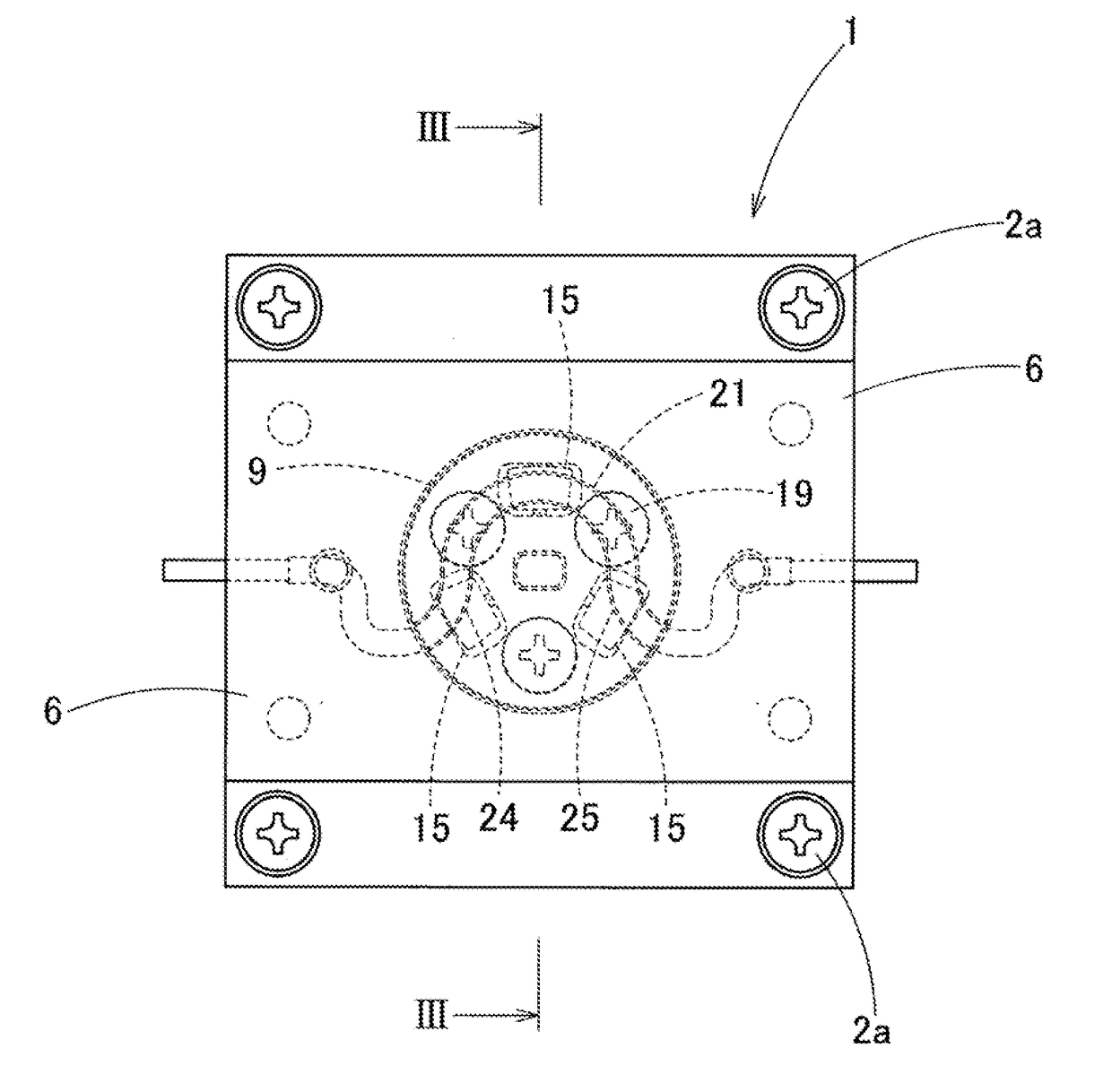
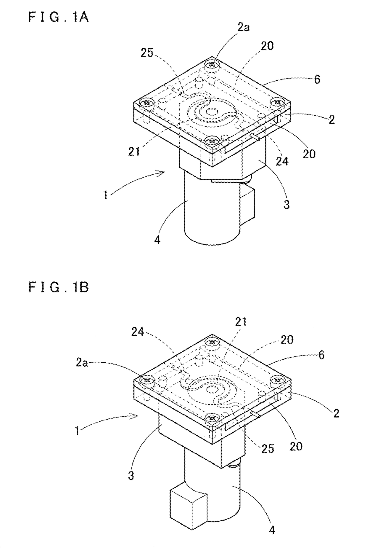
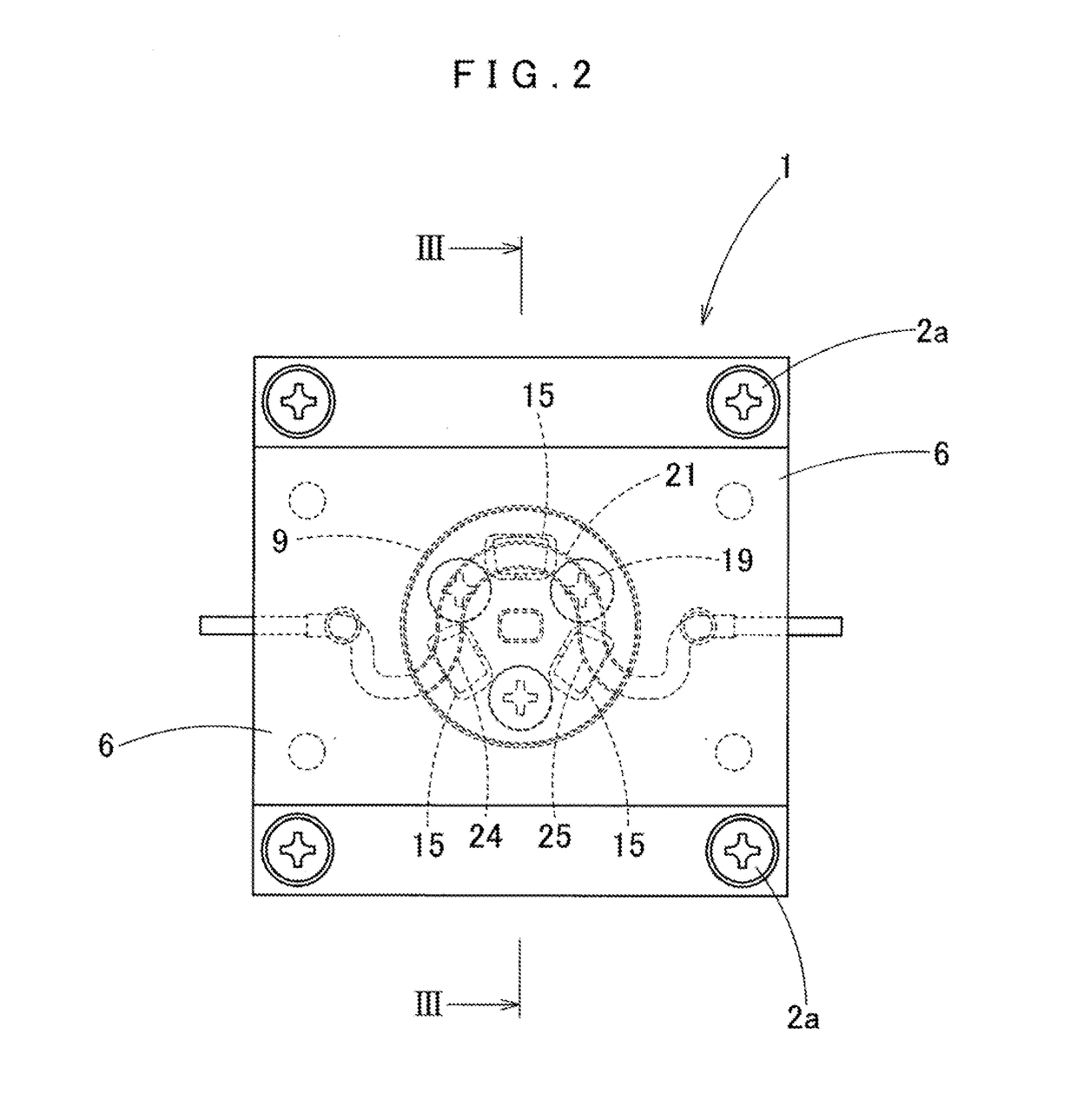
[0047]FIG. 1 to FIG. 17 show a peristaltic pump device and this peristaltic pump device includes, as shown in FIG. 15, a base 2 that houses a microfluidic chip 20, a micro peristaltic pump 1 that is fixed to a lower portion of the base 2 and drives a rotor 10 by a motor 4, and a control circuit 30 that controls a rotation speed of the motor 4.

[0048]To an upper portion of the micro peristaltic pump 1, the rotor 10 to be driven by the motor 4 is attached, and on a horizontal surface of the rotor 10, three rollers 15 are pivotally supported radially at intervals, and the three rollers 15 are pressed against a circular arc shaped flow path 21 formed inside a concave portion 27 of the microfluidic chip 20, and the rotor 10 and the rollers 15 are rotated to send a liquid at a micro flow rate.

[0049]In the micro peristaltic pump 1, schematically, a circular arc shaped flow path 21 is formed as a microfluidic flow path inside a sheet-like microfluidic chip 20, three rollers 15 of the rotor ...

second embodiment

[0089]FIG. 20 to FIG. 23 show a peristaltic pump device of a second embodiment, and FIG. 20 shows a microfluidic chip 220 of the same. In the plan views shown in FIG. 20, FIG. 21, and FIG. 23, the lines showing internal flow paths, etc., which do not appear in the plan view of the microfluidic chip 220 are shown by solid lines for easy understanding.

[0090]The microfluidic chip 220 is formed to be rectangular sheet-like from a polymeric elastic body which is soft transparent synthetic resin such as PDMS or silicone resin. A circular concave portion 227 is formed in the center of the main body of the microfluidic chip 220, and a circular arc shaped flow path 221 is formed in the concave portion 227. A radius of the circular are shaped flow path 221 is the same as the radius of the rotational trajectory 5 of the three rollers 15 (FIG. 7) on the rotor 10 (FIG. 7), and the rollers accurately roll on and press a lower surface of the circular arc shaped flow path 221. A width in the transv...

third embodiment

[0115]FIG. 24 to FIG. 26 show a microfluidic chip 320 of the peristaltic pump device. In FIG. 24 to FIG. 26, for convenience of description, a state where the inner surface of the microfluidic chip 320 is turned upward is shown, and the microfluidic chip 320 shown in the drawings is housed inside the chip housing portion 8 on the base 2 in a state turned inside out from the form shown in the drawings, to be used.

[0116]This microfluidic chip 320 is manufactured in the same manner as described above, for example, by using two polymeric elastic sheets (sheet such as a PDMS) having the same thickness, the lower sheet is superposed onto the upper sheet, and the lower sheet is molded to form a circular concave portion 327 at the center, and a circular arc shaped flow path 321 is further formed in the concave portion 327.

[0117]At that time, the circular arc shaped flow path 321 in the concave portion 327 is manufactured by bonding so as to cause a part of the lower thinner second elastic s...


PUM


Abstract

A micro peristaltic pump of a peristaltic pump device presses a rotor against a circular arc shaped flow path inside a microfluidic chip formed to be sheet-like, rotary-drives the rotor by a motor, and causes the circular arc shaped flow path to make a peristaltic motion by the rotation of the rotor, to send a fluid. The peristaltic pump device is provided with a rotation sensor that detects a rotational position of the rotor, a memory that stores in advance a rotational position of the rotor and rotation speed data of the motor corresponding to the rotational position, and a control circuit that calculates a command rotation speed of the motor from data stored in the memory based on a detection signal of the rotation sensor, and controls rotation of the motor based on the command rotation speed.

Description

BACKGROUND OF THE INVENTION1. Field of the Invention[0001]The present invention relates to a peristaltic pump device which is used at the time of flowing micro-fluid such as a culture solution or various types of reagents into a microfluidic flow path, to perform cell culturing, reagent screening, chemical analysis, and the like, and in particular, to a peristaltic pump device which is capable of effectively reducing pulsation when sending fluid.2. Description of Related Art[0002]Conventionally, a peristaltic pump in which a plurality of rollers are rotatably-pivotally supported on a circular rotor, and the outer circumferential surfaces of the respective rollers on the rotor are pressed against a tube, to send a fluid in the tube while rotating the rotor, has been known by JP No. 2004-92537 A, etc.[0003]This type of conventional peristaltic pump is configured such that a circular rotor which is rotary-driven by a motor rotatably-pivotally supports a plurality of rollers on its oute...

Claims


Application Information

Patent Timeline
Patent Type & Authority Applications(United States)
IPC IPC(8): F04B49/06F04B43/12F04B43/00F04B49/20
CPCF04B49/065F04B43/1253F04B43/0072F04B49/20F04B17/03F04B43/1261F04B43/1269F04B49/06F04B53/16
Inventor ASAI, NAOYATAKATSUKA, AKIHITOUCHIDA, KEISUKE
Owner TAKASAGO ELECTRIC
Why Eureka
Try Eureka