Manufacturing method for rolling bearing units for wheel support

a technology of rolling bearing units and manufacturing methods, which is applied in the direction of manufacturing tools, forging presses, forging/pressing/hammering apparatus, etc., can solve the problems of large load, inability to optimize the caulking and inability to meet the requirements of workpiece caulking, etc., to achieve the effect of optimizing the processing time of each workpi

Active Publication Date: 2018-05-31
NSK LTD
View PDF7 Cites 6 Cited by
  • Summary
  • Abstract
  • Description
  • Claims
  • Application Information

AI Technical Summary

Benefits of technology

[0018]According to the aspect of the present invention, it is possible to provide a manufacturing method capable of optimizing a processing time for caulking of each workpiece.

Problems solved by technology

However, in the case of such a method, a magnitude of the applied load and the time for applying the load may not be optimized for every workpiece (according to a difference in manufacturing error or property).
That is, for example, depending on a variation or the like of a protrusion amount (a protrusion length) of a portion of the cylindrical section 12 protruding from the inner end opening of the inner ring 8 in the axial direction based on the manufacturing error, there is a possibility that a load larger than a load required for applying a preload having a desired magnitude needs to be applied or the time for applying the load needs to be excessively increased.

Method used


Image

  • Manufacturing method for rolling bearing units for wheel support
  • Manufacturing method for rolling bearing units for wheel support
  • Manufacturing method for rolling bearing units for wheel support

Examples


first embodiment

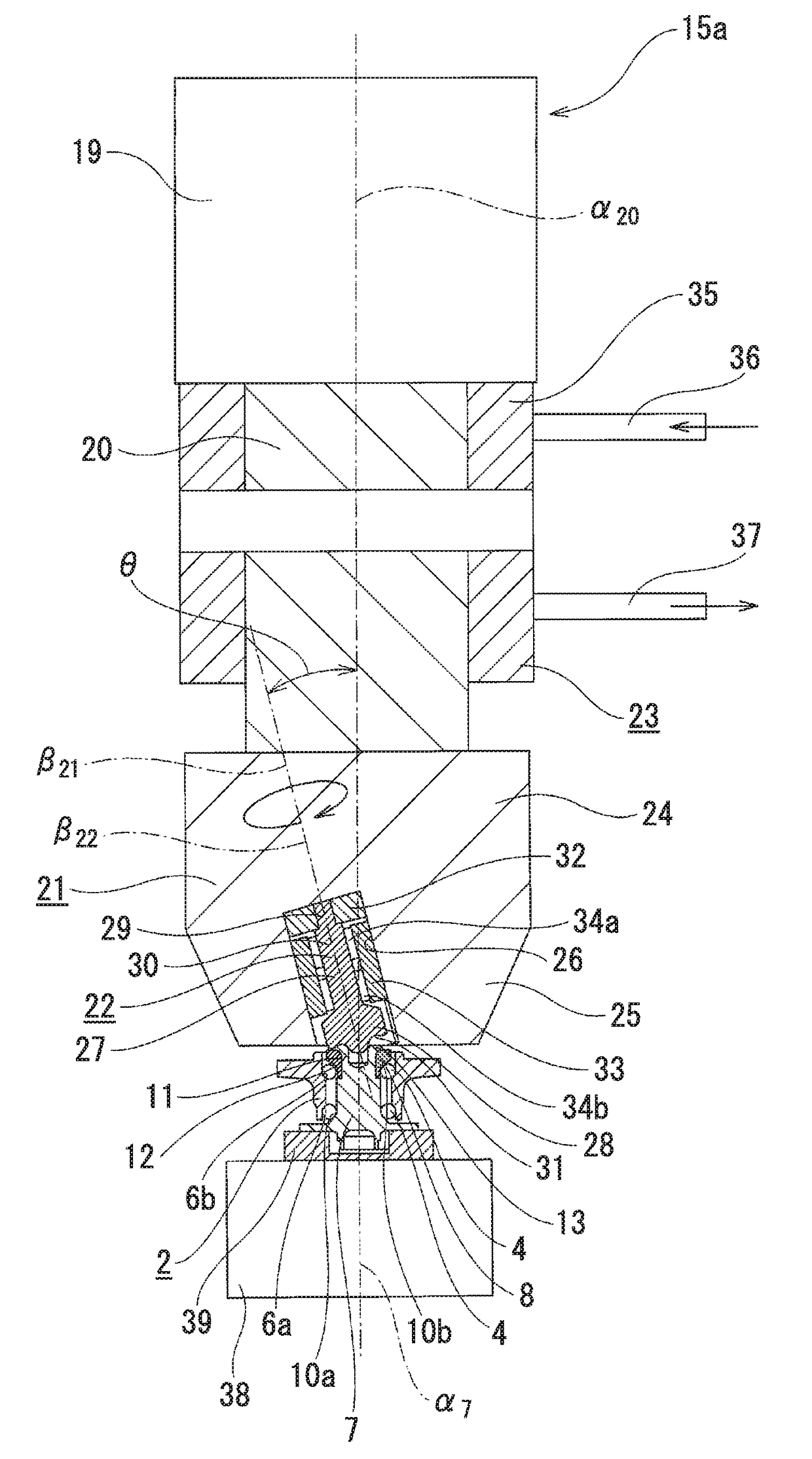
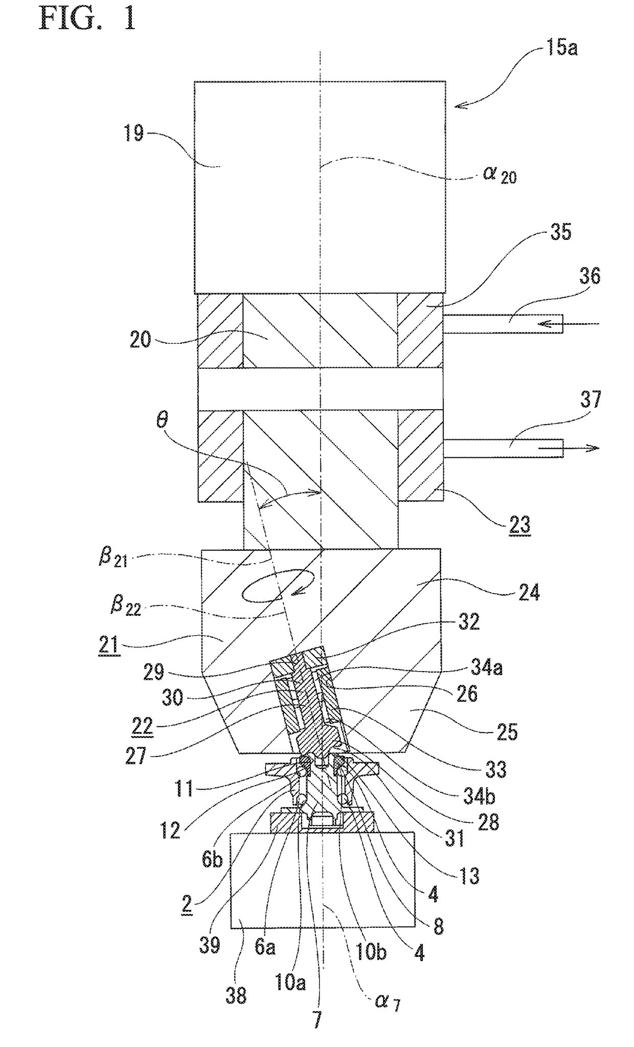
[0026]A first embodiment of the present invention will be described with reference to FIGS. 1 to 3. Hereinafter, a structure of a rotating type caulking apparatus 15a that can be used in a manufacturing method of the first embodiment will be simply described, and then the manufacturing method of the first embodiment will be described. Further, the structure of the rotating type caulking apparatus that can be used in the manufacturing method of the aspect of the present invention is not limited to the structure of the rotating type caulking apparatus 15a of the first embodiment that will be described below.

[0027]The rotating type caulking apparatus 15a used in the manufacturing method of the first embodiment includes, as shown in FIG. 1, an electric motor 19, a spindle 20, a roll holding part 21, a roll 22, a pressing device 23 and a current measuring device (not shown).

[0028]The electric motor 19 is constituted by, for example, an inverter and an induction motor in order to adjust a...

second embodiment

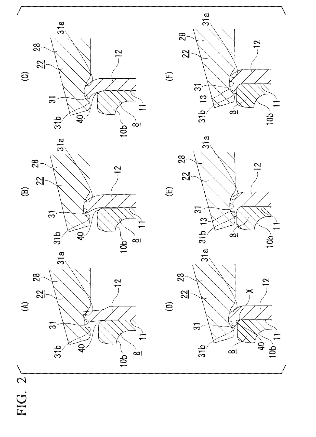
[0068]A second embodiment of the present invention will be described with reference to FIGS. 2 and 3. Even in the case of the method of manufacturing a rolling bearing unit for supporting a wheel of the embodiment, a current value flowing through the electric motor 19 during the caulking is measured.

[0069]In particular, in the case of the embodiment, after the caulking is started and the current value or the rotational torque obtained from the current value increases as shown by (II) to (IV) in FIG. 3 and abruptly decreases as shown by (V) in FIG. 3, like the portion shown by (VII) in FIG. 3, the caulking is terminated at a time point at which it is confirmed that a change of the current value (the rotational torque) converges within a predetermined range. Specifically, in the case of the embodiment, in a state in which a change amount ϵ of the current value (the rotational torque) converges within a predetermined range (−0.5≤ϵ≤0.5) for a predetermined time (in the case of the embod...


PUM

PropertyMeasurementUnit
angleaaaaaaaaaa
rotational torqueaaaaaaaaaa
current valueaaaaaaaaaa

Abstract

A method of manufacturing a rolling bearing unit for supporting a wheel includes detecting a current value flowing through an electric motor (19) configured to drive a roll (22) and determining a time to terminate a caulking process on the basis of the detected value when a caulking section (13) is formed by pressing the roll (22), inclined with respect to a central axis of a hub main body (7) and supported in a rotatable state about a central axis of the roll, against a cylindrical section (12), installed on an inner end portion of the hub main body (7) in the axial direction, while the roll (22) is rotated about the central axis of the hub main body (7).

Description

TECHNICAL FIELD[0001]The present invention relates to a method of manufacturing a rolling bearing unit for supporting a wheel in order to support a wheel of an automobile using a suspension system.[0002]Priority is claimed on Japanese Patent Application No. 2015-114567, filed Jun. 5, 2015, the contents of which are incorporated herein by reference.BACKGROUND ART[0003]FIG. 6 shows an example of a rolling bearing unit for supporting a wheel disclosed in Patent Literature 1. A rolling bearing unit 1 for supporting a wheel shown in FIG. 6 includes an outer ring 2, a hub 3, and a plurality of rolling elements (in the example shown, balls) 4 and 4.[0004]The outer ring 2 has a stationary side flange 5 formed on an outer circumferential surface thereof, and a plurality of rows of outer ring tracks 6a and 6b formed on an inner circumferential surface thereof. In addition, the hub 3 is formed by assembling a hub main body 7 and an inner ring 8. The hub main body 7 has a rotary side flange 9 f...

Claims


Application Information

Patent Timeline
Patent Type & Authority Applications(United States)
IPC IPC(8): F16C43/06B60B27/00
CPCF16C43/065B60B27/0094B60B27/0005B60B27/0084B60B2310/3142B60B2310/316B60B2310/314B21J9/025B21K25/00B60B35/02F16C19/18
Inventor HAGIWARA, NOBUYUKINAGAE, RYUSUKE
Owner NSK LTD
Why Eureka
Try Eureka