Stave with external manifold

Inactive Publication Date: 2018-05-31
BERRY METAL
View PDF4 Cites 4 Cited by
  • Summary
  • Abstract
  • Description
  • Claims
  • Application Information

AI Technical Summary

Benefits of technology

[0020]Moreover, it would be desirable to provide a stave with a central external manifold in which the stave surface temperature is uniform and which

Problems solved by technology

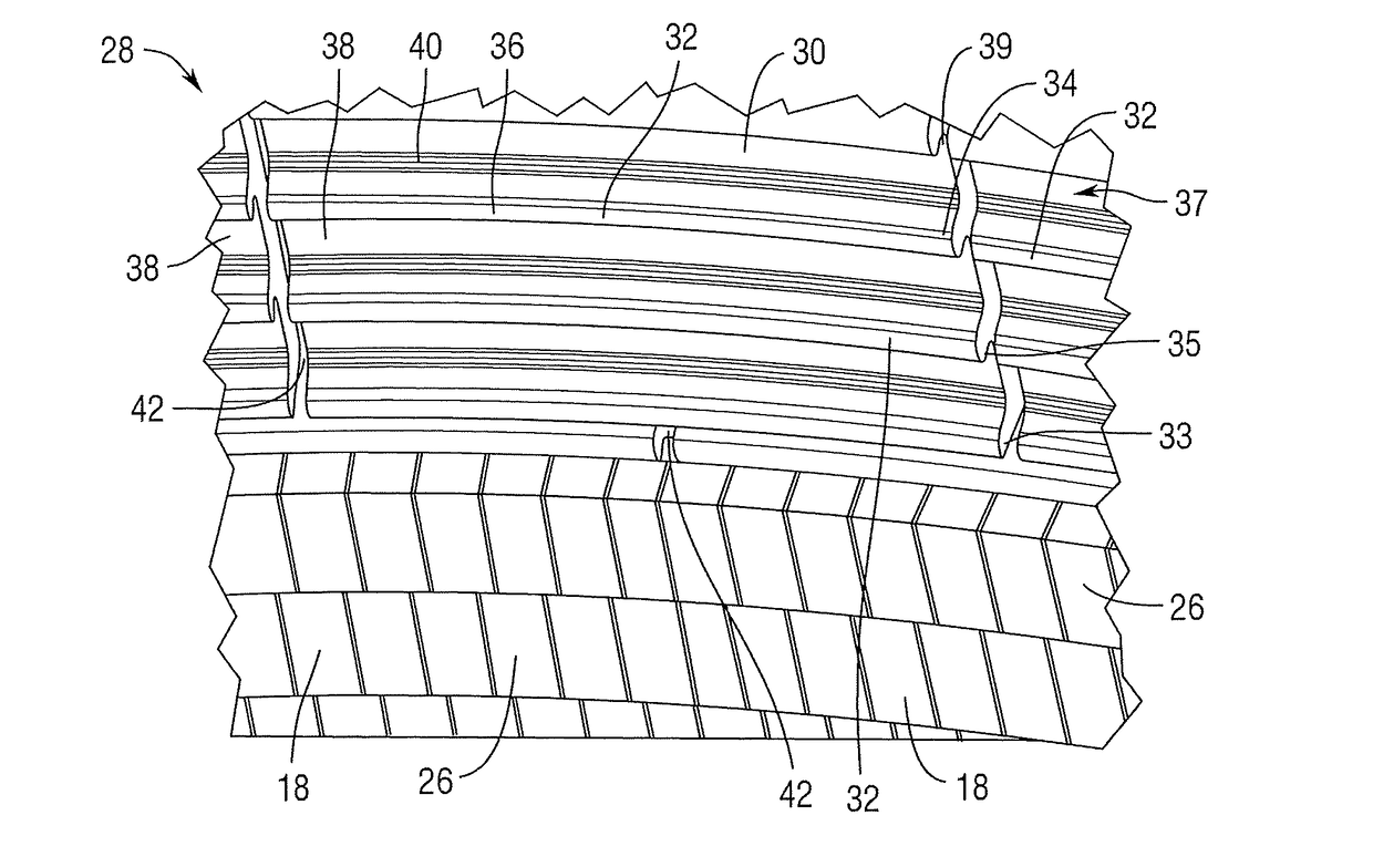
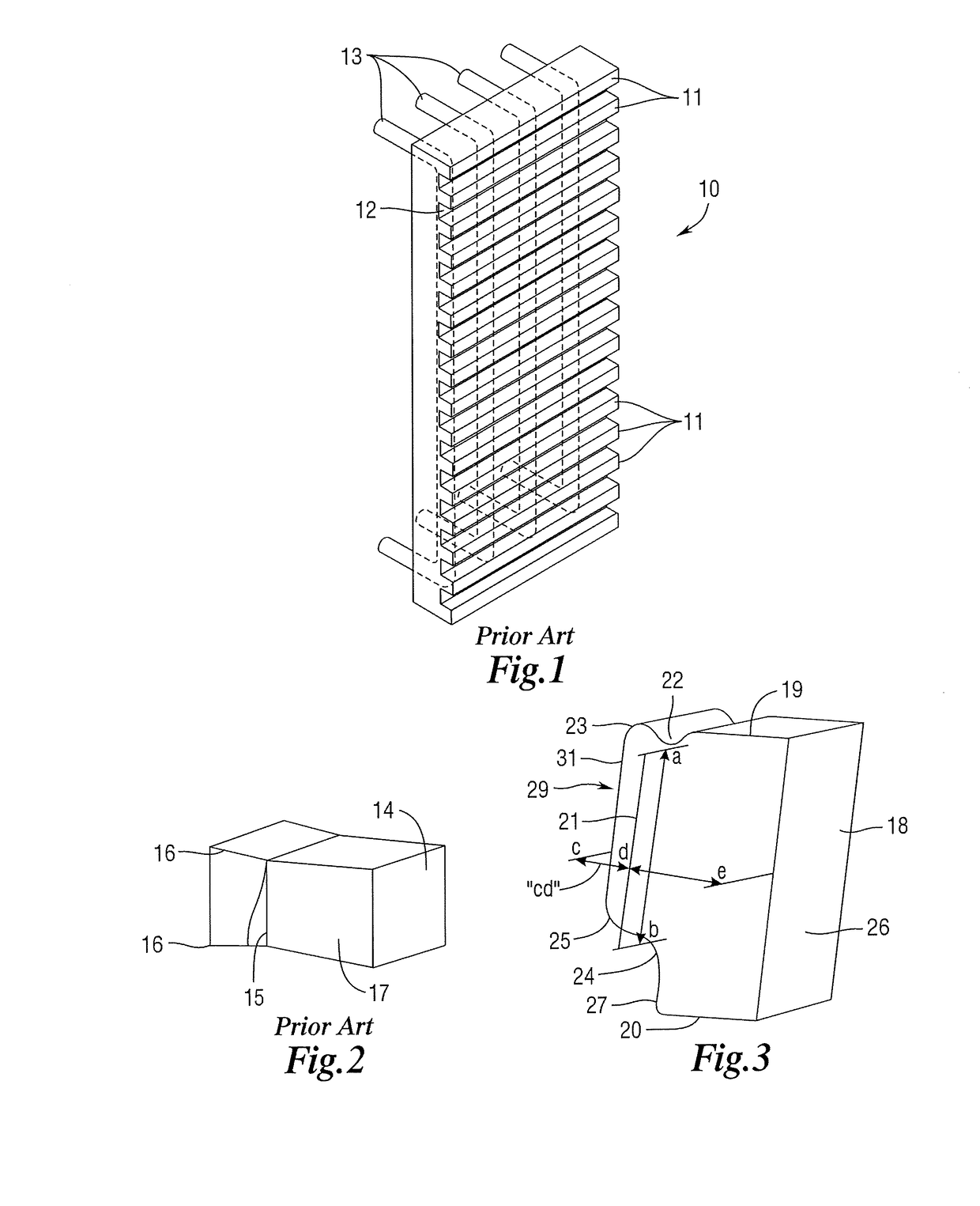
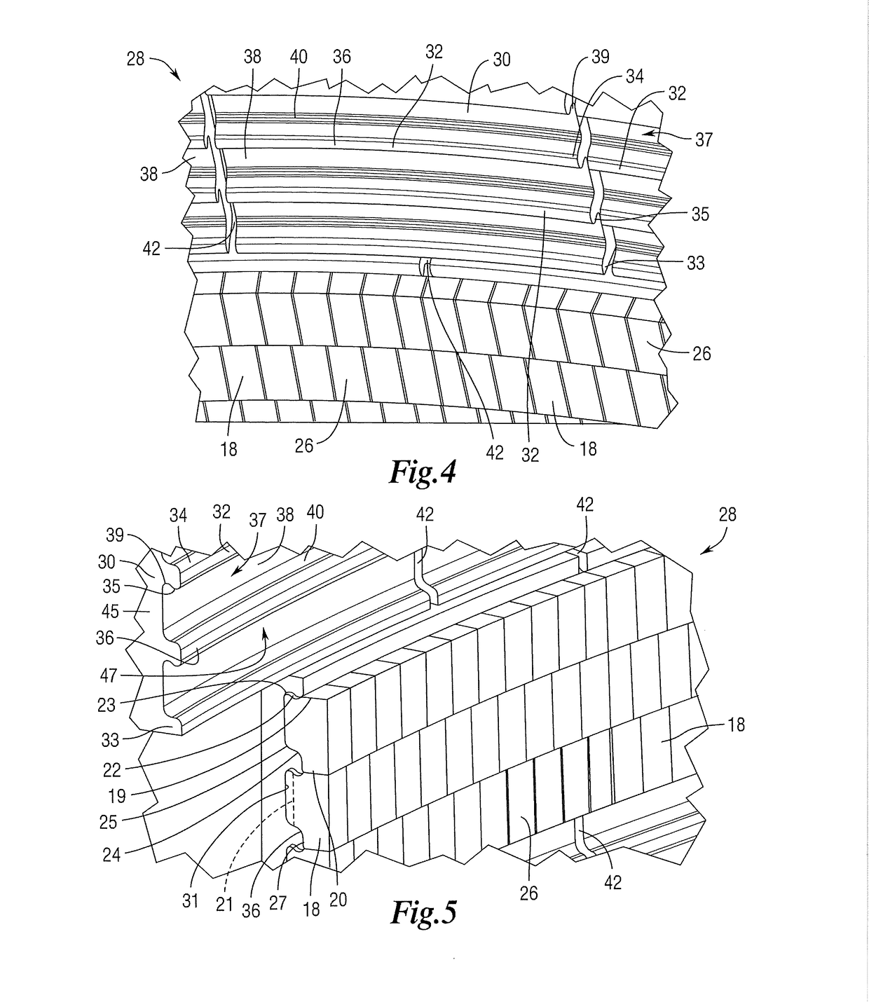
Conventional cooling staves are difficult to install in a furnace since they require multiple access holes or apertures in the furnace shell necessary for the inlet/outlet piping to and from stave through furnace shell.
Further, conventional cooling staves are relatively weak in that they are highly susceptible to the effects of expansion/contraction due to temperature changes in the furnace, particularly the effects thereof, such as weld breaches, on the individual pipe connections between the stave and the furnace shell.
During furnace operation, the ram gap often erodes prematurely and furnace gases track between the staves.
Moreover, such conventional stave/brick constructions leave brick edges protruding into the furnace which are exposed to matter and other debris falling through the furnace.
Such protruding brick edges tend to wear out more frequently than non-protruding edges, leading to broken or crumbled bricks that may

Method used


Image

  • Stave with external manifold
  • Stave with external manifold
  • Stave with external manifold

Examples


Embodiment Construction

[0066]In the following detailed description, reference is made to the accompanying examples and figures that form a part hereof, and in which is shown, by way of illustration, specific embodiments in which the inventive subject matter may be practiced. These embodiments are described in sufficient detail to enable those skilled in the art to practice them, and it is to be understood that other embodiments may be utilized and that structural or logical changes may be made without departing from the scope of the inventive subject matter. Such embodiments of the inventive subject matter may be referred to, individually and / or collectively, herein by the term “disclosure” merely for convenience and without intending to voluntarily limit the scope of this application to any single inventive concept if more than one is in fact disclosed.

[0067]The following description is, therefore, not to be taken in a limited sense, and the scope of the inventive subject matter is defined by the appende...


PUM


Abstract

A stave comprising a housing, an inner cooling fluid circuit comprising a cooling fluid inlet, a cooling fluid outlet and one or more cooling fluid pipes housed within, or cooling fluid passageways defined by, the housing, wherein each cooling fluid pipe and/or passageway is in direct or indirect fluid communication with the cooling fluid inlet and the cooling fluid outlet; and a manifold, integral with or disposed on or in the housing, that provides support for installation of the stave on a furnace shell; wherein the manifold has one or more inlet pipes, or defines one or more inlet passageways, for providing cooling fluid to the cooling fluid inlet of the cooling fluid circuit of the housing; and wherein the manifold has one or more outlet pipes, or defines one or more outlet passageways, for receiving cooling fluid from the cooling fluid outlet of the cooling fluid circuit of the housing.

Description

RELATED APPLICATIONS[0001]This application is a continuation-in-part of U.S. application Ser. No. 14 / 765,281, filed Jul. 31, 2015 entitled “STAVE WITH EXTERNAL MANIFOLD” the disclosure of which is entirely incorporated herein by reference.TECHNICAL FIELD[0002]The present disclosure relates generally to apparatus and methods for constructing and installing bricks, such as refractory bricks, in frames, staves and / or coolers in blast furnaces or other metallurgical furnaces. Related fields include systems and methods for cooling blast furnaces and other metallurgical furnaces. Related fields include cooling plates and cooling staves.BACKGROUNDField of the Disclosure[0003]Conventional designs and constructions for cooling refractory bricks in blast furnaces and other metallurgical furnaces include cooling staves.[0004]Conventional cooling staves are difficult to install in a furnace since they require multiple access holes or apertures in the furnace shell necessary for the inlet / outlet...

Claims


Application Information

Patent Timeline
IPC IPC(8): F27D1/12F27D1/06F27D1/00F27B1/14C21B7/10F28D7/08F28F1/02F28F9/02
CPCF28F9/0202F27D2009/0027F27D2009/0067F28D2021/0056F28D2021/0078F27D1/12F27D1/06F27D1/004F27B1/14C21B7/10F28D7/08F28F1/022C21B7/106C21C5/4646
Inventor SMITH, TODD G.WHITE, JAKE
Owner BERRY METAL
Why Eureka
Try Eureka