Power efficient machine diagnostic monitoring using multiple vibration sensor wireless configuration

a vibration sensor and wireless configuration technology, applied in the field of machine diagnostic data collection and analysis, can solve the problems of reducing machine performance and reliability, affecting the accuracy of low-performance vibration sensors, and affecting the reliability of machines, etc., to achieve the effect of reducing the adverse impact of such tendency to deviate, low-performance vibration, and poor accuracy

Active Publication Date: 2018-05-31
ACOEM FRANCE
View PDF18 Cites 18 Cited by
  • Summary
  • Abstract
  • Description
  • Claims
  • Application Information

AI Technical Summary

Benefits of technology

[0015]In some embodiments of the invention, the low power vibration sensor is a low performance vibration sensor. A low performance vibration sensor, as the term is used herein, is one that has technical specification ratings that do not meet the metrological requirements for the respective vibration measurements used to perform condition monitoring and diagnosis of the host machine. For example, the accuracy of the low performance vibration sensor may be poor resulting in

Problems solved by technology

Because of the importance of these machines in meeting production and service requirements, taking a machine offline unexpectedly due to a failure can be costly.
Of concern is that a machine part that is moving or being moved against eventually may fatigue or otherwise become compromised or defective resulting in decreased machine performance and reliability.
Eventually if a deteriorating condition is not detected a failure may occur.
However, implementation of permanent sensors in an effective manner has been a challenge.
In particular, the operational demands of the sensors resul

Method used


Image

  • Power efficient machine diagnostic monitoring using multiple vibration sensor wireless configuration
  • Power efficient machine diagnostic monitoring using multiple vibration sensor wireless configuration
  • Power efficient machine diagnostic monitoring using multiple vibration sensor wireless configuration

Examples


case 1 (

[0077starting at step 144) corresponds to a configuration in which a temperature threshold test is used. Case 2 (starting at step 146) corresponds to a case at which a temperature deviation is used. Referring to case 1, at step 150 the low power temperature sensor data acquisition process 76 is executed. The processor 52 activates the sensor 48 to collect temperature data. A single sample or a time-averaged sample is used as the temperature measure. The temperature measure is compared to a threshold temperature value. The specific threshold temperature is a configuration parameter set by command for the given machine 12. In addition the specific test is set by command as a configuration parameter. For some machines the test is whether the temperature measure exceeds the threshold temperature. For other machines (e.g., where test point 15 gets colder during machine operation) the test is whether the temperature measure is less than the threshold temperature. At step 152 the temperatu...

case 2 (

[0078starting at step 146) corresponds to a case at which a temperature deviation is used. For such case, the time period for collecting temperature data, the temperature deviation threshold, and the direction of temperature deviation are configuration parameters set by command according to the type of machine 12. The direction of temperature deviation is used to distinguish between a machine that is running and a machine that has recently been turned off, so that for example a machine that is cooling off after having been running hot does not trigger a finding of temperature deviation supporting a determination that the machine is running.

[0079]Referring to case 2, at step 160 the low power temperature sensor data acquisition process 76 is executed. The processor 52 activates the sensor 48 to collect temperature data. Initially, a single sample or a single time-averaged sample may be detected. Samples are to be collected over a predetermined window of time (e.g., 10 minutes, 30 min...


PUM


Abstract

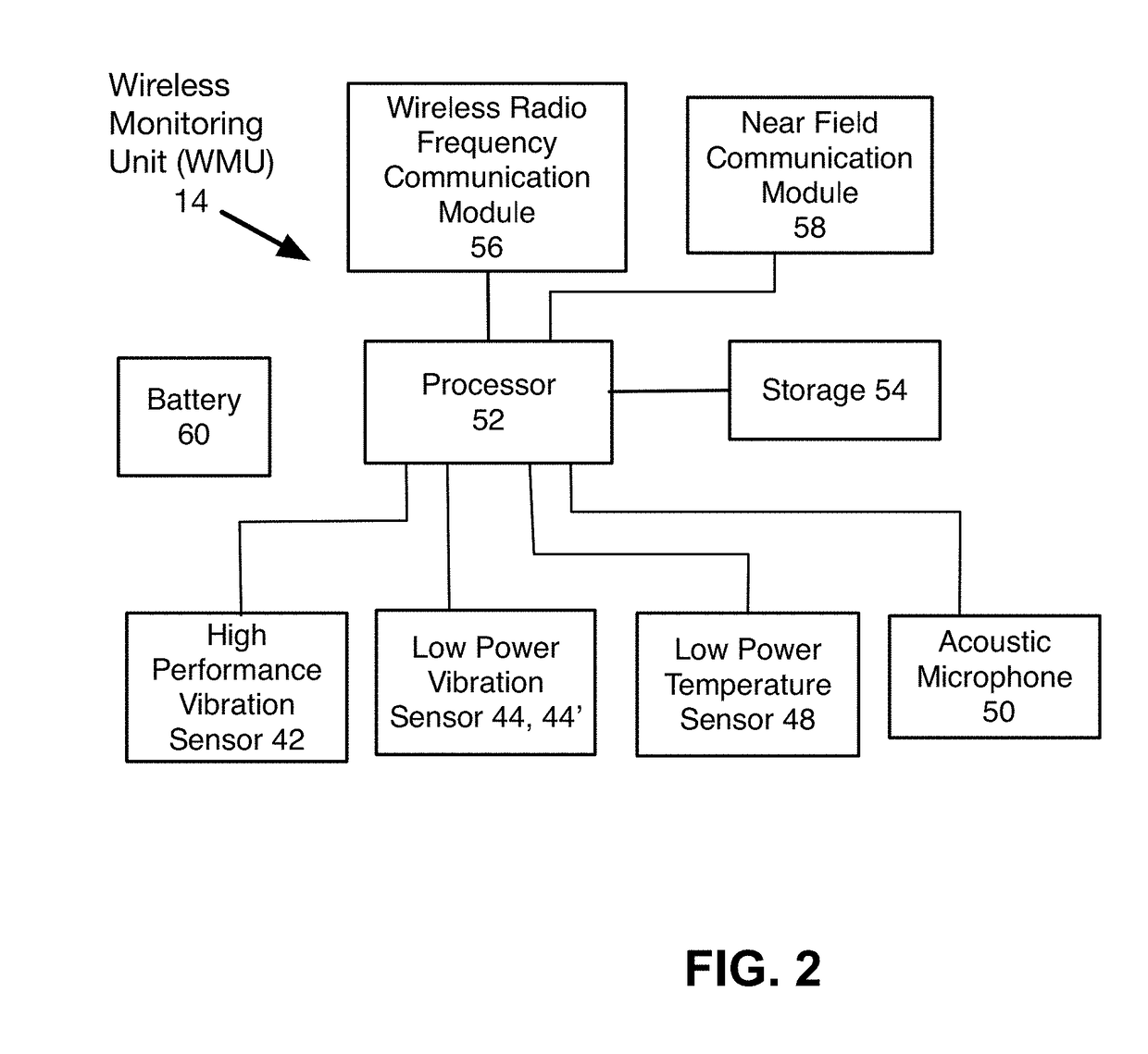
A wireless monitoring unit performs condition monitoring associated with a test point location of a host machine. The unit includes a high performance vibration sensor useful for monitoring the host machine for fault conditions and the like. The unit includes a second vibration sensor that has poorer metrological performance, but draws a comparatively insignificant amount of power from the battery. The second sensor takes a vibration measure periodically, which measure is processed to evaluate whether the machine is in a state eligible to undergo a health assessment. Diagnostic monitoring using the high performance vibration sensor is enabled only when the host machine it is in the eligible state. A low power temperature sensor provides additional data for guarding against a false trigger, in effect allowing the processor to distinguish against vibration from another machine propagating to the host machine causing the host machine to vibrate while the host machine is not running.

Description

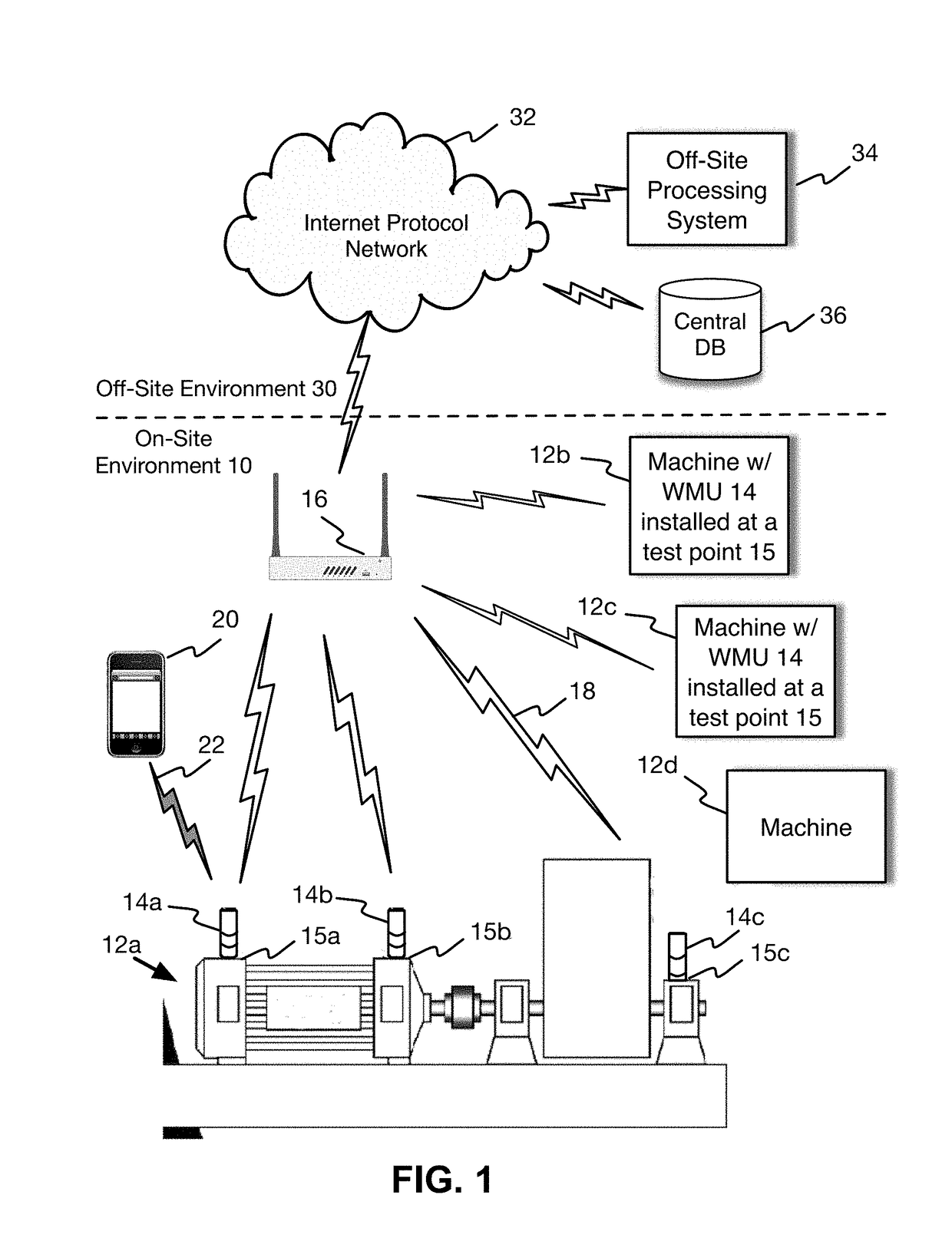
RELATED SPECIFICATION[0001]This application is related to commonly-assigned, U.S. patent application Ser. No. ______ of Wascat et al. filed on the same day (Attorney Docket No. AC1.P103) for “Power-Efficient Data-Load-Efficient Method of Wirelessly Monitoring Rotating Machines,” and is incorporated herein in its entirety by reference. The specification of commonly-assigned, U.S. patent application Ser. No. 14 / 451,777 of Wascat et al. filed on Aug. 4, 2014 for Automatic Rotating-Machine Fault Diagnosis With Confidence Level Indication” is incorporated herein in its entirety by referenceBACKGROUND OF THE INVENTION[0002]This invention relates generally to the collection and analysis of machine diagnostic data, such as vibration data, temperature, and rotation speed. More particularly, this invention relates to a wireless monitoring unit installed at a rotating machine for collecting and analyzing machine diagnostic data.[0003]Many types of machines are used in a production or manufactu...

Claims


Application Information

Patent Timeline
IPC IPC(8): G01H1/00G01K13/00H04W4/00
CPCH04W4/70H04W4/005G01K13/00G01H1/00G01K3/005H04W4/38Y02D30/70G01H1/003G01M1/28G01M13/028G01M13/045G01M15/12G05B23/0221G08C17/00G08C17/02
Inventor WASCAT, BERTRANDMAZOYER, THIERRYLABEYRIE, PATRICKLAVAURE, GUILLAUMEPOIZAT, PHILIPPE
Owner ACOEM FRANCE
Why Eureka
Try Eureka