

Flexible display device
a display device and flexible technology, applied in the field of flexible display devices, can solve the problems of less consumption of power, and achieve the effect of ensuring product stability and reliability
- Summary
- Abstract
- Description
- Claims
- Application Information
AI Technical Summary
Benefits of technology
Problems solved by technology
Method used
Image

Examples
first embodiment
[0058]Hereinafter, a flexible display device according to a first example embodiment of the present invention will be described with reference to FIGS. 6 to 8. FIG. 6 is a cross-sectional view of a flexible display device according to the first example embodiment of the present invention. FIG. 7 is a plane view illustrating the shape of a protective film according to the first example embodiment of the present invention. FIG. 8 is a plane view showing a location relationship between a first film, a circuit unit, and a protective film according to the first example embodiment of the present invention.
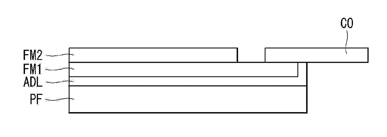
[0059]With reference to FIG. 6, the flexible display device according to the first example embodiment of the present invention includes a first substrate FM1, a second substrate FM2, a circuit unit CO, and a protective film PF.
[0060]The first substrate FM1 may be formed of a flexible material which is able to bend. For example, the first substrate FM1 may be formed of polyimide (PI), pol...
second embodiment
[0079]Hereinafter, a flexible display device according to a second example embodiment of the present invention will be described with reference to FIGS. 9 to 12. FIGS. 9 and 10 are cross-sectional views of the flexible display device according to the second embodiment of the present invention. FIG. 11 is a cross-sectional view of a flexible display device according to a comparison example. FIG. 12 is a plane view of the flexible display device according to the second example embodiment of the present invention.
[0080]With reference to FIG. 9, the flexible display device may include a first substrate FM1, a second substrate FM2, a circuit unit CO, and a first protective film PF1. The first substrate FM1 may be formed of a flexible material which is able to bend. For example, the first substrate FM1 may be formed of polyimide (PI), polyethylene terephthalate (PET), polyethylene naphthalate (PEN), polycarbonate (PC), polyethersulfone (PES), polyarylate (PAR), polysulfone (PSF), ciclic-o...
third embodiment
[0101]Hereinafter, a flexible display device according to a third example embodiment of the present invention will be described with reference to FIGS. 13 and 14. FIGS. 13 and 14 are cross-sectional views of the flexible display device according to the third example embodiment of the present invention.
[0102]With reference to FIG. 13, a first protective film PF1 is formed to embrace the bottom surface of a first substrate and the circumference of the side surfaces thereof. The flexible display device may block moisture and oxygen, which could come inside from the side surfaces of a first adhesion layer ADL1, and therefore, the flexible display device may improve product reliability and stability.
[0103]In FIG. 13, the first protective film PF1 is depicted as being bent along the shape of the first substrate FM1, but aspects of the present embodiments are not limited thereto. When the first substrate FM1 and a second substrate FM2 have a sufficiently thin thickness and the first protec...
PUM
 Abstract
Description
Claims
Application Information