Dye-sensitized solar cell

a solar cell and dye technology, applied in the field can solve the problems of decreasing energy conversion efficiency, insufficient to prevent the aggregation and adsorption of dyes, and improving the reliability and efficiency of dye sensitization solar cells, so as to secure the reliability and efficiency of dye sensitized solar cells, prevent the decrease of fill factor, and prevent the effect of

Inactive Publication Date: 2019-10-24
DONGJIN SEMICHEM CO LTD
View PDF2 Cites 0 Cited by
  • Summary
  • Abstract
  • Description
  • Claims
  • Application Information

AI Technical Summary

Benefits of technology

[0009]In order to solve the problems of the prior art, it is an object of the present invention to provide a dye-sensitized solar cell that can improve reliability and efficiency of a dye-sensitized solar cell by forming a membrane.
[0011]The present invention forms a membrane on the surface of a working electrode to prevent a dye from being separated from an oxide semiconductor layer, and thus can secure reliability and efficiency of a dye-sensitized solar cell.
[0012]The present invention also forms the membrane on the surface of a counter electrode so that electrolyte elements (I−, I3−, etc) may be passed through, but the dye may not be adsorbed, thereby preventing a decrease in a fill factor (FF) due to hyperabsorption of the dye, and thus, can secure the reliability and efficiency of a dye-sensitized solar cell.
[0013]In addition, the membrane forms a transparent film on the surface of an electrode, thereby maximizing visibility due to the transparency of the dye-sensitized solar cell.

Problems solved by technology

In this case, the electrons react with the redox electrolyte solution, do not rotate along the circuit, and inefficiently disappear, and on the surface of the conductive film, the electrons generated by light are also consumed by the reaction with the redox electrolyte, thus decreasing energy conversion efficiency.
Thus, in the prior art, a technology of forming an insulation layer on the surface of the oxide semiconductor and on the surface of the conductive film exposed through the dye so as to prevent adsorption between the dye and the oxide semiconductor has been disclosed, but it was insufficient to prevent the aggregation and adsorption of the dye to improve the reliability and efficiency of a dye-sensitized solar cell because it cannot surround the surface of the dye.

Method used


Image

  • Dye-sensitized solar cell
  • Dye-sensitized solar cell
  • Dye-sensitized solar cell

Examples


example 1

[Example 1] Preparation of a Dye-Sensitized Solar Cell

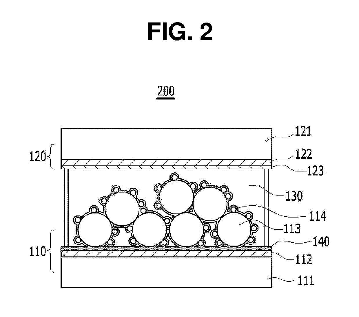
[0046]A dye-sensitized solar cell including a working electrode on which a membrane is formed, as shown in FIG. 2, was prepared by a common preparation process of a dye-sensitized solar cell, except that the surfaces of a working electrode, that is, the surface of a conductive substrate, the surface of an oxide semiconductor layer (TiO2) formed on the working electrode, and the surface of a dye adsorbed on the surface of the oxide semiconductor layer, were dipped in a solution including isooctyltrimethoxysilane.

[0047]Herein, the working electrode was treated with an isooctyltrimethoxysilane solution, after the dye was adsorbed.

[0048]The conditions were as follows.

[0049]On FTO glass, a DTY5 photoelectrode paste (8 μm, Dongjin Semichem Co., Ltd., Korea) was coated by a doctor blade method. The paste on the photoelectrode was calcined at 450° C. for 30 minutes to form a TiO2 thin film layer with a thickness of 8 μm.

[0050]The calcine...

example 2

[Example 2] Preparation of a Dye-Sensitized Solar Cell

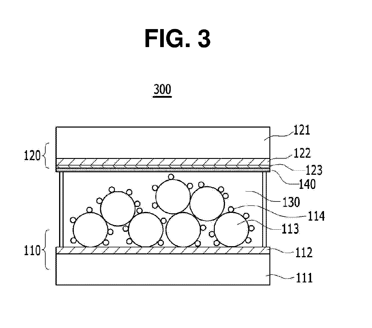
[0052]A dye-sensitized solar cell including a counter electrode on which a membrane is formed, as shown in FIG. 3, was prepared by a common preparation process of a dye-sensitized solar cell, except that the surface of a counter electrode was dipped in a solution including isooctyltrimethoxysilane.

[0053]Herein, the counter electrode was treated with an isooctyltrimethoxysilane solution, after platinum was formed.

[0054]The conditions were as follows.

[0055]On FTO glass, a DTY5 photoelectrode paste (8 μm, Dongjin Semichem Co., Ltd., Korea) was coated by a doctor blade method. The paste on the photoelectrode was calcined at 450° C. for 30 minutes to form a TiO2 thin film layer with a thickness of 8 μm.

[0056]The calcined thin film layer was immersed in a dye solution in which 0.2 mM of D35 was dissolved in mixed solvents of acetonitrile and t-butyl alcohol at a volume ratio of 1:1, at room temperature for 20 hours. The TiO2 thin film ...

experiment 1

[Experiment 1] Comparison of the Properties of Dye-Sensitized Solar Cells

[0060]In order to evaluate the performance of a dye-sensitized solar cell, the properties (open circuit voltage (Voc), current density (Jsc), fill factor (FF), and photo conversion efficiency (η)) of the dye-sensitized solar cells prepared in Example 1 and Comparative Example 1 were measured and are shown in the following Table 1 and FIG. 5.

TABLE 1Voc (V)Jsc (mA / cm2)FF (%)η (%)Example 10.76010.3773.525.79Comparative0.72910.0576.405.59Example 1

[0061]As shown in Table 1, it was confirmed that when a membrane was formed on all the surfaces of a working electrode including the surface of a oxide semiconductor layer and the surface of the dye, the recombination of electrons was prevented, and thus the open circuit voltage was increased and the separation of dye was prevented, and thus, the current density was improved and the efficiency of a cell was generally increased.


PUM


Abstract

The present invention relates to a dye-sensitized solar cell electrode and a dye-sensitized solar cell including the same. A membrane is formed on a surface of a working electrode, thereby preventing a dye from being separated from an oxide semiconductor layer. The membrane is formed on a surface of a counter electrode, thereby enabling electrolyte elements (I−, I3−, etc.) to be passed therethrough while not allowing the dye to be adsorbed. The reliability and efficiency of a dye-sensitized solar cell be improved.

Description

CROSS-REFERENCE TO RELATED APPLICATIONS[0001]This application is a continuation application of International Application No. PCT / KR2017 / 015765 filed on Dec. 29, 2017, which claims priority to Korean Application No. 10-2016-018449 filed on Dec. 30, 2016. The applications are incorporated herein by reference.TECHNICAL FIELD[0002]The present invention relates to a dye-sensitized solar cell, and particularly to a dye-sensitized solar cell that can improve reliability and efficiency by forming a membrane.BACKGROUND ART[0003]The descriptions below provide only the background information relating to the present invention, and do not constitute the prior art.[0004]A dye-sensitized solar cell mainly consists of a substrate, a conductive film, a working electrode including an oxide semiconductor and a dye, an electrolyte, and a counter electrode. The dye is adsorbed to the oxide semiconductor represented by TiO2, and electrons that receive light and are excited are injected into the TiO2. The...

Claims


Application Information

Patent Timeline
Patent Type & Authority Applications(United States)
IPC IPC(8): H01G9/20
CPCH01G9/2027H01G9/2022H01G9/2068H01G9/2059H01G9/2004Y02E10/542H01G9/2031H01G9/2077
Inventor KIM, YOUNG MIKIM, JONG BOKBAEK, JONG GYUSHIN, KYU SOON
Owner DONGJIN SEMICHEM CO LTD
Why Eureka
Try Eureka