Double u-core switched reluctance machine

a reluctance machine and switch technology, applied in the direction of dynamo-electric machines, electrical apparatus, magnetic circuits, etc., can solve the problems of mutual coupling, and large amount of end windings obtained

Inactive Publication Date: 2018-05-31
AALBORG UNIV
View PDF5 Cites 9 Cited by
  • Summary
  • Abstract
  • Description
  • Claims
  • Application Information

AI Technical Summary

Benefits of technology

[0011]The advantages of the first aspect, of the double U-core are that the amount of end winding is reduced and that the end windings of each phase are physically completely independent on each other, resulting in compact end windings which are easier to cool and which exhibits minimal mutual coupling. The result is a compact stator segment which may be pre-wound before assembly of the stator. Further more, the number of stator segments is halved when utilising double U-cores compared to using four separate U-cores.
[0019]Advantage of the embodiment is a reduced acoustic noise and improved thermal capabilities.
[0021]Advantage of this embodiment is to improve the structural stiffness of the machine.
[0023]An advantage of the embodiment is that the density of the filling material provides a dampening effect on the structure of the double U-core SRM.

Problems solved by technology

However the prior art has the disadvantage that large amount of end windings is obtained.
It was found that the longer end windings resulted in excessive copper losses, mutual coupling, as well as increased 3D effects.
Furthermore, it was found that excessive eddy current losses are present in the wedges containing the cooling channels, as well as the stator housing, surrounding the U-cores.
However, the solution suffers from the fact, that the copper present on the outside of the legs do not add to the mmf produced, hence this can effectively be seen as end winding.

Method used


Image

  • Double u-core switched reluctance machine
  • Double u-core switched reluctance machine
  • Double u-core switched reluctance machine

Examples


Embodiment Construction

[0044]The present invention will now be explained in further details. While the invention is susceptible to various modifications and alternative forms, specific embodiments have been disclosed by way of examples. It should be understood, however, that the invention is not intended to be limited to the particular forms disclosed. Rather, the invention is to cover all modifications, equivalents, and alternatives falling within the spirit and scope of the invention as defined by the appended claims.

[0045]In the following a double U-core Switched Reluctance Machine (SRM) is presented and the elements of the SRM is disclosed.

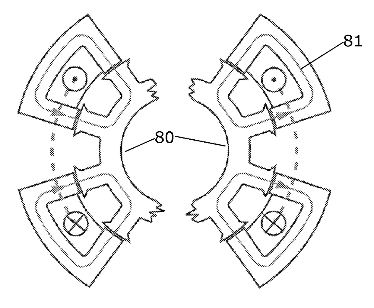
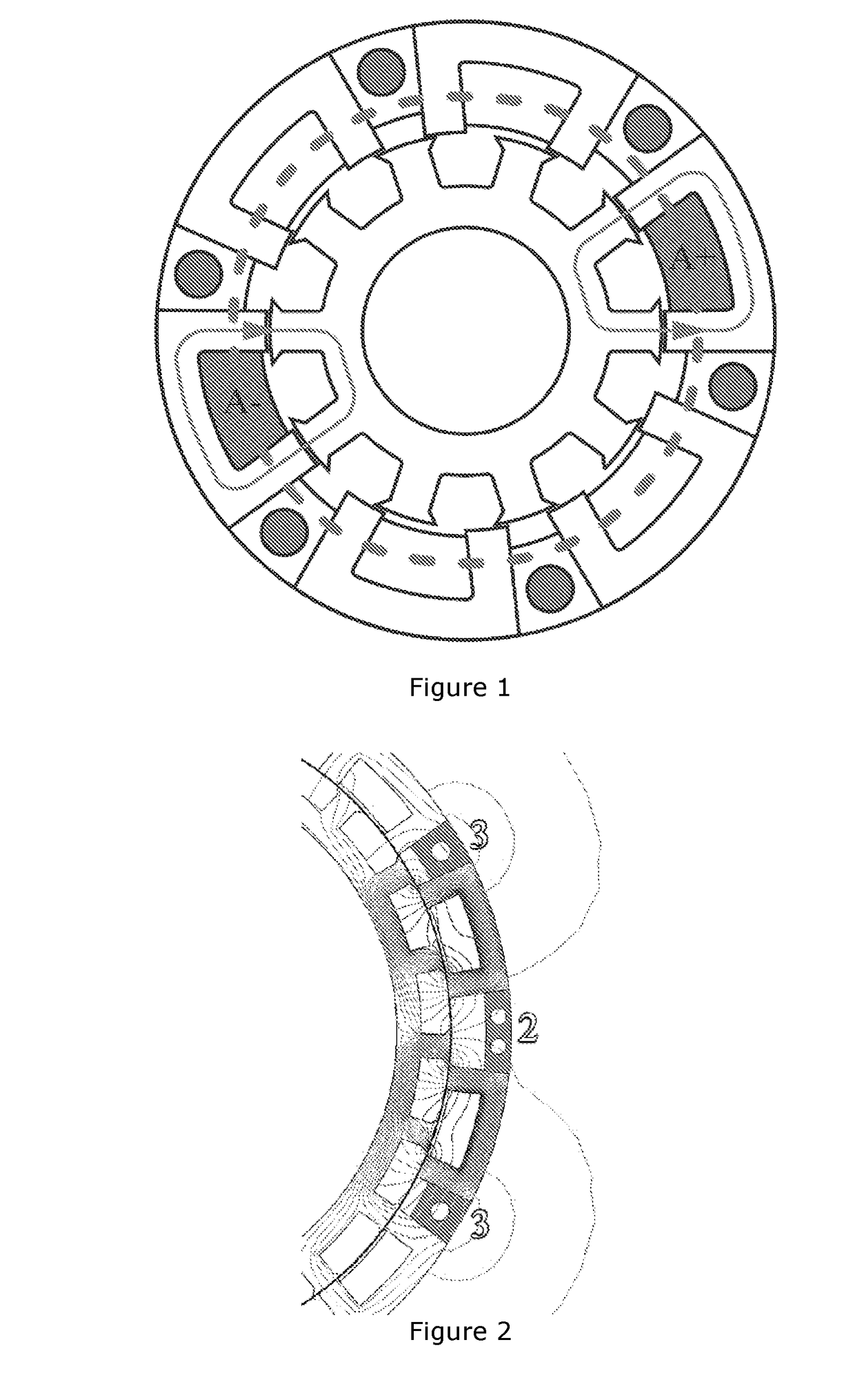
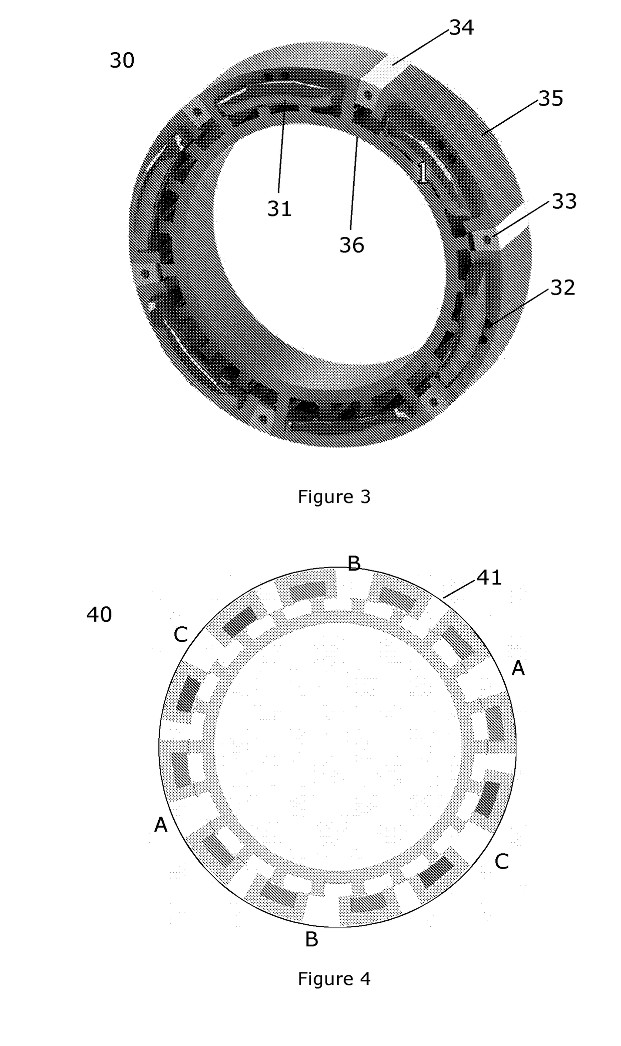
[0046]The following embodiments relates to a switched reluctance machine (SRM), utilising a topology, which has the advantages of shorter flux path, less magnetic coupling, short end windings, magnetic gearing, and the possibility of internal cooling. In extend to the specific topology, it also maintains the advantages of the conventional SRM, which is great efficie...


PUM


Abstract

The present invention relates to an electrical machine stator comprising a plurality of stator segments (131,132,133), each segment comprises a first U-core and a second U-core wound with a winding, where the winding being arranged with at least one coil turn, each coil turn comprises a first axial coil segment and a second axial coil segment and one or more end segments, wherein the first and second axial coil segments are arranged in opposite directions to each other, and where the first U-core receives the first axial coil segment(s) and the second U-core receives the second axial coil segment(s), wherein the first U-core and the second U-core are located adjacent to each other, whereby the winding spans the first and second U-cores. The invention also relates to a SRM machine with a stator mentioned above and a rotor.

Description

FIELD OF THE INVENTION[0001]The present invention relates to a switched reluctance machine (SRM).BACKGROUND[0002]The background of the invention is the U-core technology presented in U.S. Pat. No. 7,312,549. U.S. Pat. No. 7,312,549 solves many of the known problems of conventional SRM. The flux path of the machine is much shorter, the magnetic mutual coupling between the phases is lower. However the prior art has the disadvantage that large amount of end windings is obtained.[0003]It was found that the longer end windings resulted in excessive copper losses, mutual coupling, as well as increased 3D effects. Furthermore, it was found that excessive eddy current losses are present in the wedges containing the cooling channels, as well as the stator housing, surrounding the U-cores.[0004]US 20120306297 shows a machine which proposes the use of PI-cores, which are wound around the legs of the stator cores. However, the solution suffers from the fact, that the copper present on the outsi...

Claims


Application Information

Patent Timeline
Patent Type & Authority Applications(United States)
IPC IPC(8): H02K1/14H02K1/24H02K3/18H02K7/116H02K1/18H02K1/20H02K19/10
CPCH02K1/148H02K1/246H02K3/18H02K7/116H02K1/185H02K1/20H02K19/103H02K7/083H02K1/14H02K1/141H02K5/1735H02K5/1737H02K7/085H02K7/086H02K2201/12
Inventor RASMUSSEN, PETERKONGERSLEV, KRISTIANJAEGER, RASMUSNIELSEN, SIMON STAAL
Owner AALBORG UNIV
Why Eureka
Try Eureka