Cooling structure for vane

Active Publication Date: 2018-06-14
DOOSAN HEAVY IND & CONSTR CO LTD
View PDF26 Cites 19 Cited by
  • Summary
  • Abstract
  • Description
  • Claims
  • Application Information

AI Technical Summary

Benefits of technology

[0011]Accordingly, the present disclosure has been made in view of the above-mentioned problems, and an object thereof is to enhance cooling performance by improving a st

Problems solved by technology

Hence, there is a problem in that cooling performance is increasingly degraded in the downstream side.
In addition, the insert is thermally expanded due to an increase in temperature of air in the insert according to the ope

Method used


Image

  • Cooling structure for vane
  • Cooling structure for vane
  • Cooling structure for vane

Examples


Embodiment Construction

[0051]Exemplary embodiments of the present disclosure will be described below in more detail with reference to the accompanying drawings. The embodiments may be provided in different forms and the present disclosure should not be construed as limited to the embodiments set forth herein. Throughout the disclosure, like reference numerals refer to like parts throughout the various figures and embodiments.

[0052]Hereinafter, a gas turbine vane according to an embodiment of the present disclosure will be described in detail with reference to the accompanying drawings.

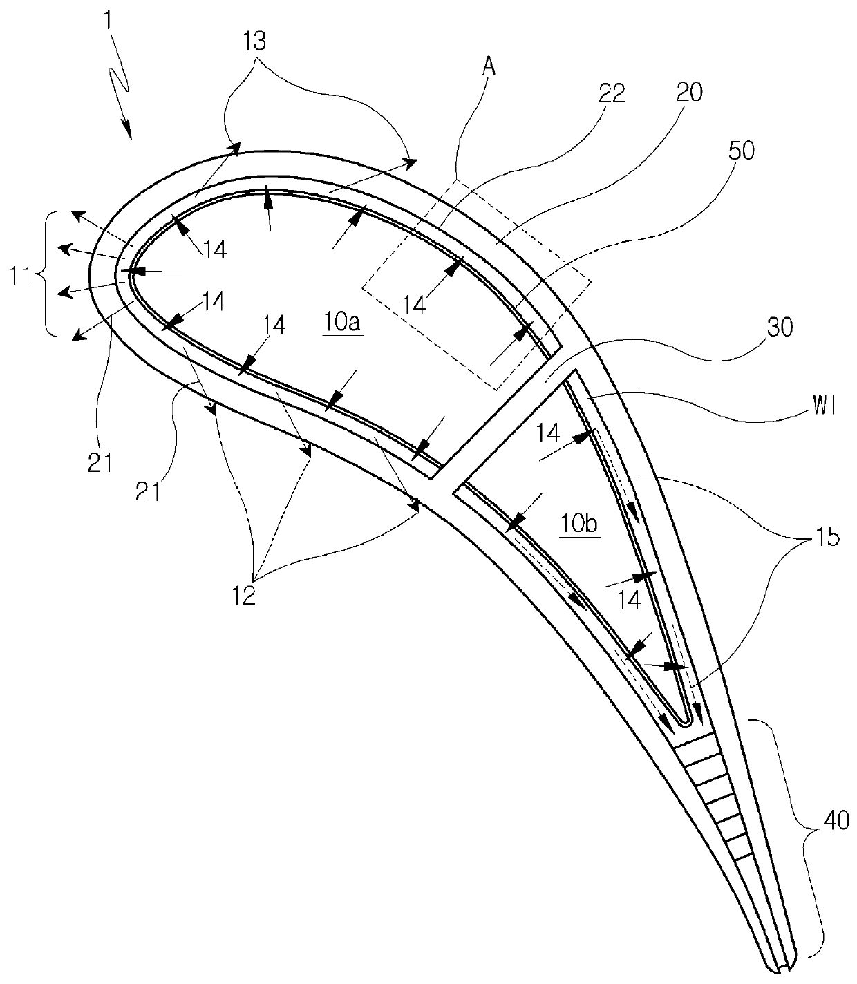
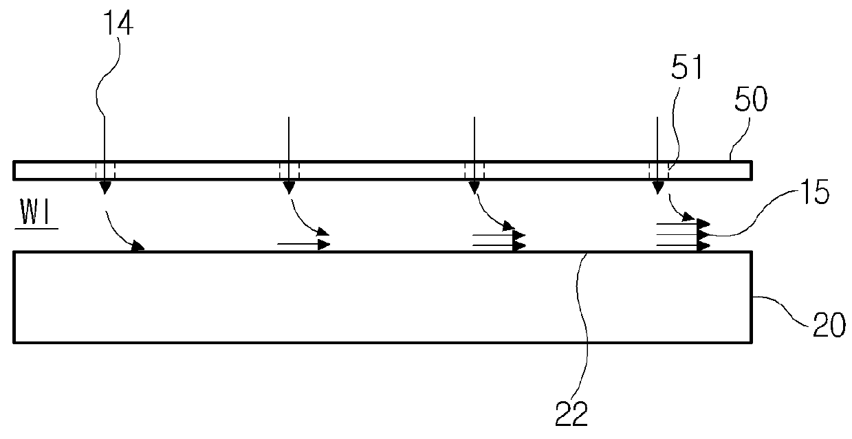
[0053]FIG. 3 is a horizontal cross-sectional view illustrating a gas turbine vane according to an embodiment of the present disclosure. The vane, which is designated by reference numeral 1, a sidewall 20 that defines an airfoil shape, a partition 30 that partitions a path in which an introduced cooling fluid flows, an insert 50 that is disposed within the sidewall 20 at a distance from an inner surface 22 of the sidewall, an...


PUM


Abstract

A gas turbine vane includes a sidewall having a plurality of film holes formed therein and defining an airfoil having a leading edge and a trailing edge, a cut-back formed at the trailing edge of the airfoil defined by the sidewall, an insert spaced apart from an inner surface of the sidewall and installed within the sidewall while having a plurality of insert holes formed therein, and a plurality of posts extending from the sidewall. The plurality of insert holes are formed in a plurality of rows, the insert holes of each row are arranged at a distance from the leading edge to the trailing edge, and a surface of the insert is positioned on the posts.

Description

CROSS-REFERENCE TO RELATED APPLICATION[0001]This application claims priority to Korean Patent Application No. 10-2016-0166949, filed on Dec. 8, 2016, the disclosure of which is incorporated herein by reference in its entirety.BACKGROUND[0002]Exemplary embodiments of the present disclosure relate to a structure for cooling a gas turbine, and more particularly, to an impingement cooling structure in a gas turbine vane.[0003]In general, a gas turbine includes a compressor that compresses air, a combustor that mixes the compressed air with fuel for ignition, and a turbine blade assembly that produces electric power.[0004]The combustor is operated at a high temperature above 2,500° F. The vane and blade of the turbine are typically exposed to the high temperature, and they are thus made of a material resistant to high temperature. In addition, the vane and blade of the turbine are provided with a cooling system that prolongs their life and reduces a possibility of damage due to excessive...

Claims


Application Information

Patent Timeline
IPC IPC(8): F01D5/18F23R3/00F01D25/12
CPCF01D5/189F23R3/002F01D25/12F23R2900/03044F05D2260/202F05D2240/303F23R2900/03043F01D5/18F01D5/187F01D5/188F05D2240/127F05D2260/201F05D2260/2212F05D2260/22141F01D5/186
Inventor BANG, MYEONG HWAN
Owner DOOSAN HEAVY IND & CONSTR CO LTD
Why Eureka
Try Eureka