
Scanning Head with Integrated Beam Position Sensor and Adjustment Arrangement for an Off-Line Adjustment

a scanning head and position sensor technology, applied in the field of scanning heads, can solve the problems of high cost, high complexity of adjustment, and inability to adjust the system, and achieve the effect of high quality and rapid adjustmen

Active Publication Date: 2018-06-21
SCANLAB GMBH
View PDF4 Cites 9 Cited by
  • Summary
  • Abstract
  • Description
  • Claims
  • Application Information

AI Technical Summary

Benefits of technology

This patent is about a scanner head for laser material processing that has a beam position system to adjust the position of the laser beam. The beam position system can detect and correct external errors caused by components upstream of the scanner head, allowing for faster and more accurate offline adjustments. The adjustment device includes a computing unit and a scanner head with movable optical elements controlled by the beam position system. This allows for precise and rapid adjustment without needing to influence external units. Overall, the scanner head is a self-supporting system that can be mounted and adjusted independently of the customer's framework conditions.

Problems solved by technology

The disadvantage here is that an adjustment of the system can take place exclusively through components that are upstream of the mirror assembly in the direction of propagation of the laser beam.
Such an adjustment is highly complex, protracted, and expensive.

Method used


Image

  • Scanning Head with Integrated Beam Position Sensor and Adjustment Arrangement for an Off-Line Adjustment
  • Scanning Head with Integrated Beam Position Sensor and Adjustment Arrangement for an Off-Line Adjustment
  • Scanning Head with Integrated Beam Position Sensor and Adjustment Arrangement for an Off-Line Adjustment

Examples


first embodiment

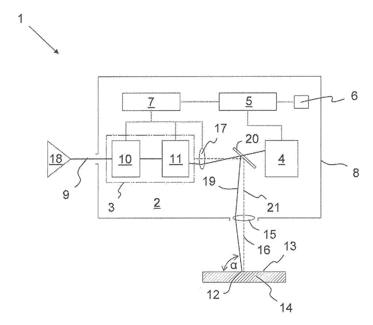
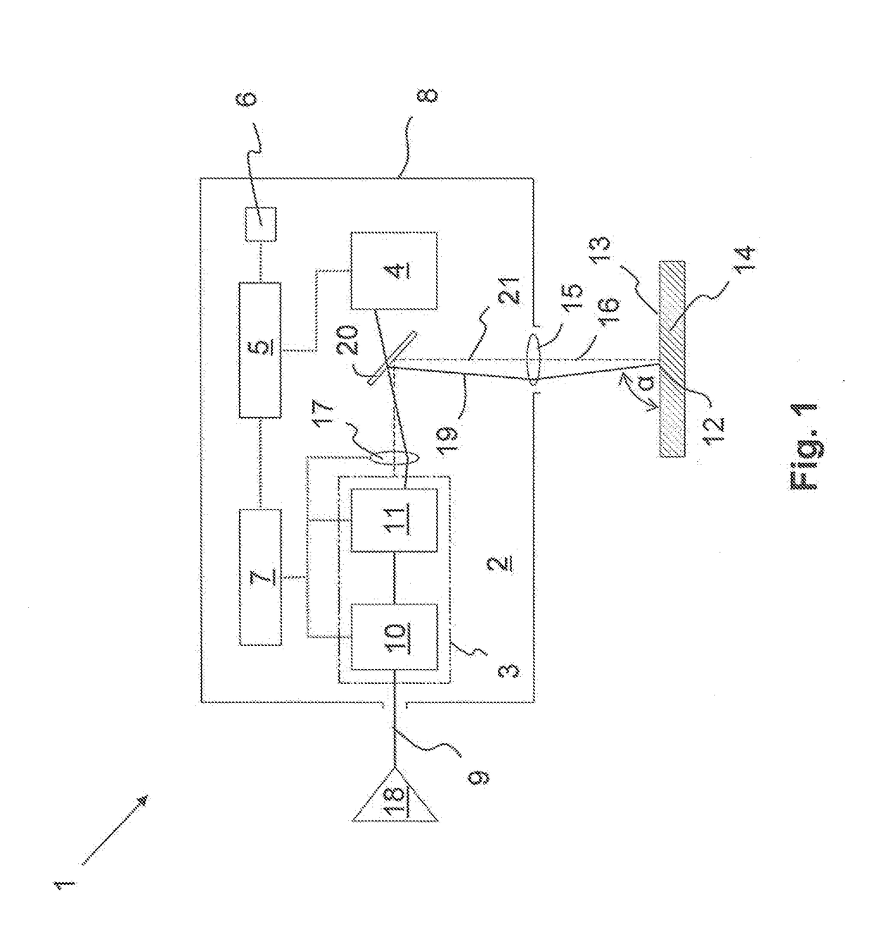
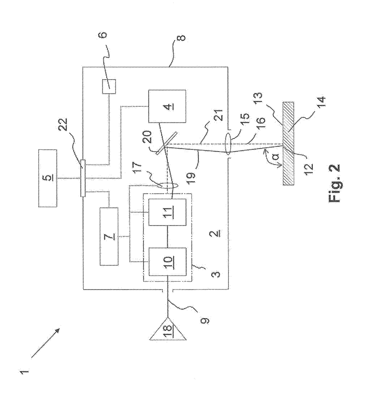
[0051]One problem with the start-up on the customer's side of the scanner head 2 is that the laser beam 9 generated by a laser source 18 enters the scanner head 2 in a misaligned manner. Thus, even with a beam positioning system 3 properly calibrated at the factory, such adjustment error continues in direction of propagation of the beam across all components of the scanner head 2; that is, across the parallel offset unit 10 and the deflection unit 11. In order to correct this adjustment error coupled in front of the beam position system 3, according to the embodiment shown in FIG. 1, the scanner head 2 comprises at least parts of the adjustment device 1, whereas, the adjustment device is completely integrated into the scanner head 2.

[0052]Herein, the beam position sensor 4 forms a component of the adjustment device. With the beam position sensor 4, an actual position 19 of the laser beam 9 in the area of the beam path between the beam position system 3 and the focusing optics 15 ca...

second embodiment

[0068]FIG. 6 shows the beam position system 3, with which the beam position can be adjusted by means of two double-axis mirrors 30a, 30b, which can be tilted around two axes of rotation. Four degrees of setting freedom for the beam position are provided by the two times two degrees of freedom of mirror tilting. Such embodiment of the beam position system 3 is an additional example of a beam position system that is not built from two subsystems, but provides the functions of the parallel displacement and the tilt of the beam in a manner integrated into a single mirror unit.

[0069]With the preceding embodiments, the propulsion of the mirror by means of galvanometer drives is particularly advantageous in order to allow a highly dynamic and at the same time highly accurate adjustment of the beam position. The galvanometer drives in the beam position system 3 are operated in online operation, preferably in a closed loop position control, which is carried out independently of the beam posi...


PUM

PropertyMeasurementUnit
angle of incidenceaaaaaaaaaa
optical axisaaaaaaaaaa
angleaaaaaaaaaa

Abstract

A scanner head for laser material processing with a laser beam includes focusing optics, and a beam position system that influences a position of the laser beam and is upstream of the focusing optics in a direction of propagation of the laser beam. The beam position system includes at least two controllable movable optical elements by means of which an angle of incidence of the laser beam on a processing surface of a workpiece is adjustable. A processing location of the laser beam on the processing surface is also movable in two dimensions. A beam position sensor is downstream of the beam position system and is configured to detect an actual position of the laser beam or at least four independent position parameters of the laser beam.

Description

FIELD OF THE INVENTION[0001]The present invention relates to a scanner head for laser material processing with focusing optics and a beam position system for influencing the laser beam position, which is upstream of the focusing optics in the direction of propagation of the laser beam, which comprises at least two controllable movable optical elements and by means of which an angle of incidence of the laser beam on the processing surface is dynamically adjustable, and the processing location of the laser beam is dynamically movable on the processing surface in two dimensions. Furthermore, the invention relates to an adjustment device with such a scanner head along with an adjustment process for offline adjustment.BACKGROUND[0002]The above-mentioned scanner heads are used for various purposes, in particular for marking, labeling, for abrasive and / or structuring processing, for cutting, for drilling, for sintering, or for welding. For various applications of laser material processing,...

Claims


Application Information

Patent Timeline
Patent Type & Authority Applications(United States)
IPC IPC(8): B23K26/082B23K26/03B23K26/06
CPCB23K26/082B23K26/032B23K26/0643B23K26/0648B23K26/0665B23K26/043
Inventor SONNER, CHRISTIANRABE, MATTHIAS
Owner SCANLAB GMBH
Learn More