Core conveying device and core conveying method

a conveying device and core technology, applied in the direction of manufacturing tools, foundry patterns, moulding apparatus, etc., can solve the problems of deviating and the relative positions between the core and the gripping parts may deviate from each other, so as to achieve accurate conveying, accurate disposed, and accurate conveying of the core

Active Publication Date: 2018-06-21
TOYOTA JIDOSHA KK
View PDF0 Cites 6 Cited by
  • Summary
  • Abstract
  • Description
  • Claims
  • Application Information

AI Technical Summary

Benefits of technology

[0015]In the core conveying device and the core conveying method according to the first aspect and the second aspect of the present disclosure, the support section of the core conveying device slides in the horizontal direction with respect to the moving device. Therefore, when the support section is moved downward so as to grip the core, as the positioning pin provided on the mounting table abuts against the inner surface of the hole of the support section and the support section slides in the horizontal direction with respect to the moving device, the position of the support section in the horizontal direction with respect to the core is determined. That is, when the gripping part is disposed at a grip position of the core, the support section is moved by the moving device to dispose the gripping part at the grip position of the core. However, in this case, there is a case where the relative positions between the core and the gripping part may deviate from each other. In the present disclosure, the support section is configured to slide in the horizontal direction with respect to the moving device, and as the positioning pin provided on the mounting table abuts against the inner surface of the hole of the support section and the support section slides in the horizontal direction with respect to the moving device, the position of the support section in the horizontal direction with respect to the core is determined. Therefore, since the gripping part can be accurately disposed at the grip position of the core, the core can be accurately conveyed.
[0016]According to the aspect of the present disclosure, the core conveying device and the core conveying method capable of accurately conveying a core can be provided.

Problems solved by technology

However, when the gripping parts are disposed at the grip position of the core, the relative positions between the core and the gripping parts may deviate from each other.
However, in this case, there is a case where the relative positions between the core and the gripping part may deviate from each other.

Method used


Image

  • Core conveying device and core conveying method
  • Core conveying device and core conveying method
  • Core conveying device and core conveying method

Examples


embodiment 1

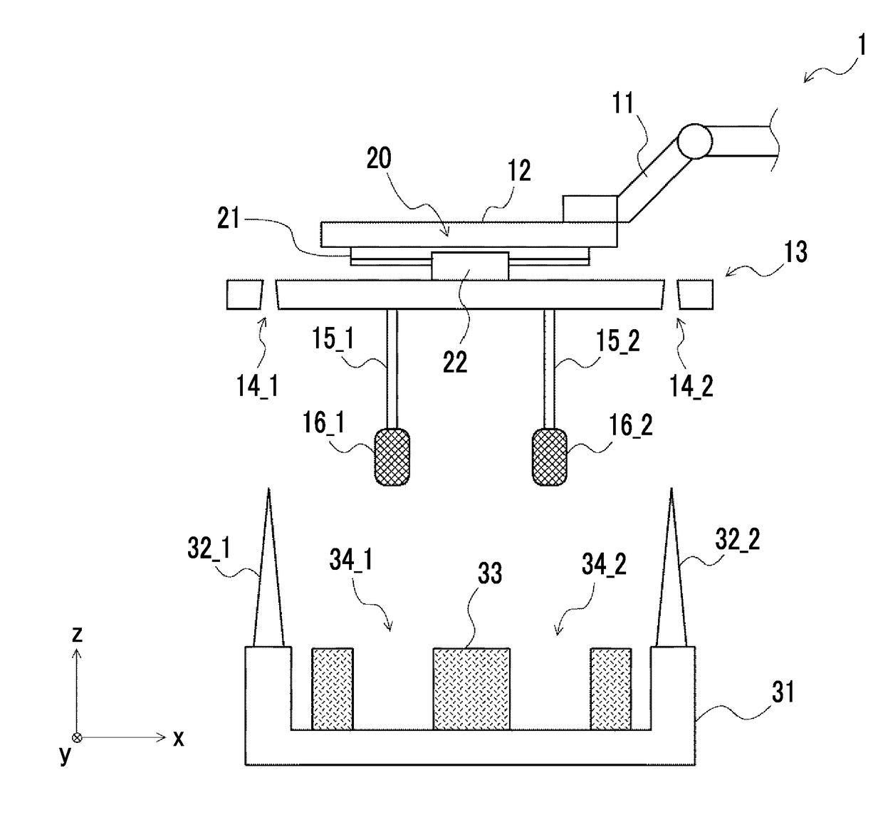
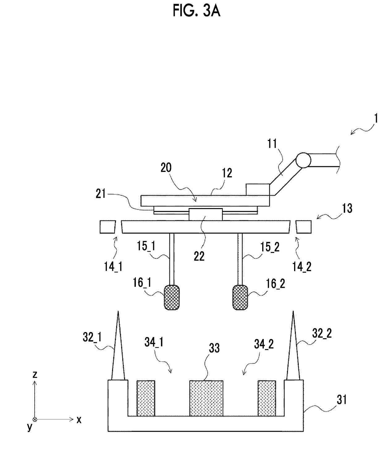
[0047]Hereinafter, embodiments of the present disclosure will be described with reference to the drawings. FIG. 1 is a view illustrating a core conveying device according to Embodiment 1. As illustrated in FIG. 1, a core conveying device 1 includes a robot arm 11, a movable unit (moving device) 12, a support section 13, holding devices 15_1, 15_2, and a mounting table 31.

[0048]The robot arm 11 is configured to be capable of moving the movable unit 12 in x, y, and z axial directions. For example, the robot arm 11 moves the movable unit 12 in a state where an upper surface of the movable unit 12 maintains a parallel state with respect to a horizontal plane (xy plane).

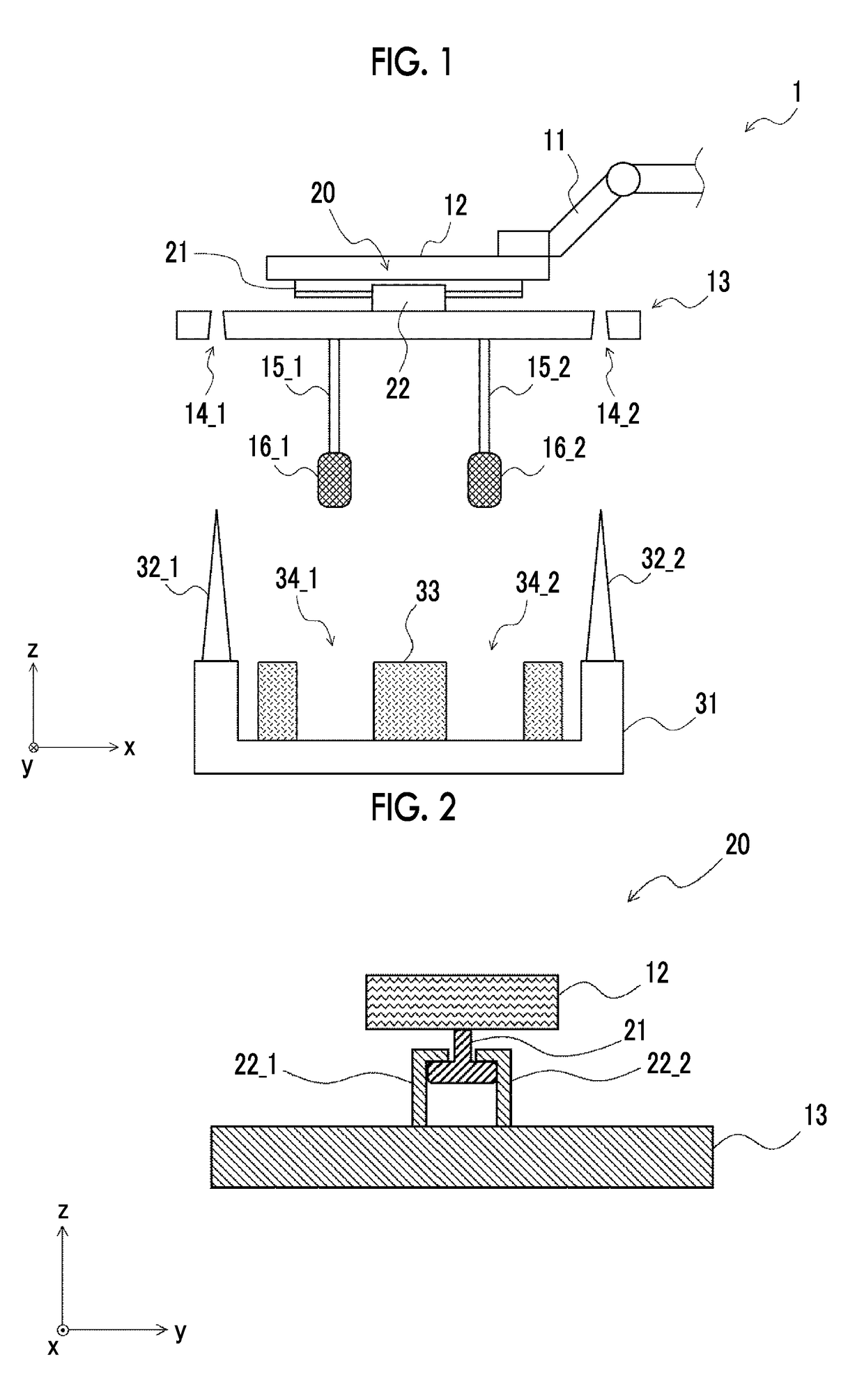
[0049]The movable unit 12 and the support section 13 are coupled together via a sliding mechanism 20. That is, the support section 13 is configured to be capable of sliding in a horizontal direction, i.e., in an x-axial direction with respect to the movable unit 12.

[0050]FIG. 2 is a sectional view for describing the detai...

embodiment 2

[0079]Next, Embodiment 2 of the present disclosure will be described. FIG. 6 is a sectional view for describing a sliding mechanism provided in a core conveying device according to Embodiment 2. The core conveying device according to Embodiment 2 is different from the core conveying device described in Embodiment 1 in that a sliding mechanism 25 includes a fixing device (electromagnet 23). Since the core conveying device according to Embodiment 2 is the same as the core conveying device described in Embodiment 1 except this difference, the same constituent elements will be designated by the same reference signs, and the duplicate description thereof will be omitted.

[0080]Also in the core conveying device 2 according to the present embodiment, the movable unit 12 and the support section 13 are coupled together via the sliding mechanism 25. That is, the support section 13 is configured to be capable of sliding in the horizontal direction, i.e., in the x-axial direction with respect to...

embodiment 3

[0098]Next, Embodiment 3 of the present disclosure will be described. FIGS. 8A to 8C are plan views for describing an operation when a core conveying device according to Embodiment 3 conveys a core. In the present embodiment, as illustrated in FIGS. 8A to 8C, an operation in a case where a core 70 including first to third portions 71 to 73 is gripped will be described. In addition, since the core conveying device to be described in the present embodiment is the same as the core conveying device described in Embodiments 1 and 2, duplicate description will be omitted.

[0099]Additionally, in FIGS. 8A to 8C, so as to simplify the drawings, solely the support section 13, the holes 14_1, 14_2, and gripping parts 61_1 to 61_6 of the core conveying device are illustrated, and illustration of the other constituent elements is omitted. Additionally, the support section 13 and the holes 14_1, 14_2 are illustrated by dashed lines.

[0100]As illustrated in FIGS. 8A to 8C, the core 70 includes the f...


PUM

PropertyMeasurementUnit
sizeaaaaaaaaaa
shapeaaaaaaaaaa
diameteraaaaaaaaaa

Abstract

A core conveying device includes a plurality of holding devices, a support section, a moving device, and a mounting table. The support section has a hole formed at a position corresponding to a positioning pin and is connected so as to slide in a horizontal direction with respect to the moving device. A size of a lower end opening of the hole is larger than a size of an upper end of the positioning pin. The support section is configured such that, when the support section is moved downward so as to grip the core, as the positioning pin abuts against an inner surface of the hole and the support section slides in the horizontal direction with respect to the moving device, a position of the support section in the horizontal direction with respect to the core is determined.

Description

INCORPORATION BY REFERENCE[0001]The disclosure of Japanese Patent Application No. 2016-247723 filed on Dec. 21, 2016 including the specification, drawings and abstract is incorporated herein by reference in its entirety.BACKGROUND1. Technical Field[0002]The present disclosure relates to a core conveying device and a core conveying method.2. Description of Related Art[0003]A core for casting is a mold used to form a hollow part in a casting to be produced. In the related art, the core is manually fitted in the mold. However, as the accuracy of the casting becomes higher, it is becoming more crucial to dispose the core in the mold with high accuracy. For this reason, a technique for disposing the core in the mold with high accuracy is becoming crucial.[0004]Japanese Unexamined Patent Application Publication (Translation of PCT Application) No. 05-509071 (JP 05-509071 A) discloses a technique regarding a conveying device for conveying a core for casting.SUMMARY[0005]As one of the metho...

Claims


Application Information

Patent Timeline
Patent Type & Authority Applications(United States)
IPC IPC(8): B65G47/90B25J15/00
CPCB66C1/46B65G47/90B25J15/0023B22C23/00B22C9/108B22D45/00B25J15/0047B25J17/0233B65G47/908
Inventor KIKUCHI, MAKOTOITO, TSUBASATANAKA, YOSHITAKANAKAHASHI, TADASHI
Owner TOYOTA JIDOSHA KK
Why Eureka
Try Eureka