Multi-view-angle image capturing device and multi-view-angle image inspection apparatus using the same

a multi-view angle, image-capturing technology, applied in the direction of image enhancement, instruments, optical elements, etc., can solve the problems of image inspection, data compression along the edge of the object, and the difficulty of processing an image of a curved surface object, etc., to achieve the effect of insufficient detection efficiency and high equipment cos

Inactive Publication Date: 2018-06-21
UTECHZONE CO LTD
View PDF16 Cites 2 Cited by
  • Summary
  • Abstract
  • Description
  • Claims
  • Application Information

AI Technical Summary

Benefits of technology

[0005]The aim of the present invention is to address the issue of the conventional inspection of surfa

Problems solved by technology

As is well known in the art, it is difficult to process an image of a curved-surface object under inspection, the main reason being that when an inspection apparatus takes an image of a curved-surface object, the curved surface tends to result in data compression along the edge of the object.
Even when images are ta

Method used


Image

  • Multi-view-angle image capturing device and multi-view-angle image inspection apparatus using the same
  • Multi-view-angle image capturing device and multi-view-angle image inspection apparatus using the same
  • Multi-view-angle image capturing device and multi-view-angle image inspection apparatus using the same

Examples


first embodiment

[0036]Three different embodiments of the image augmentation modules of the present invention are described below by way of example. Please refer to FIG. 4 to FIG. 7 for various views of the first embodiment to begin with.

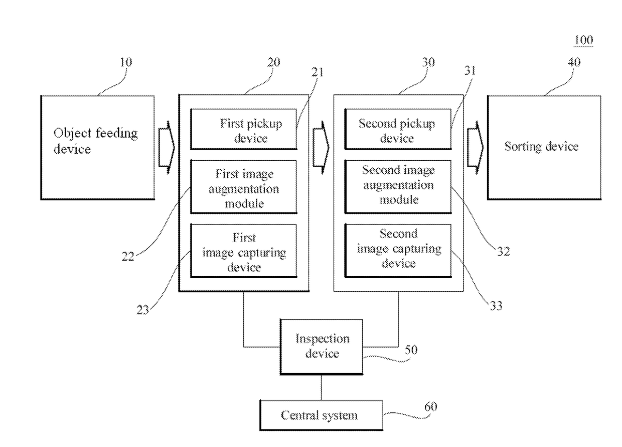
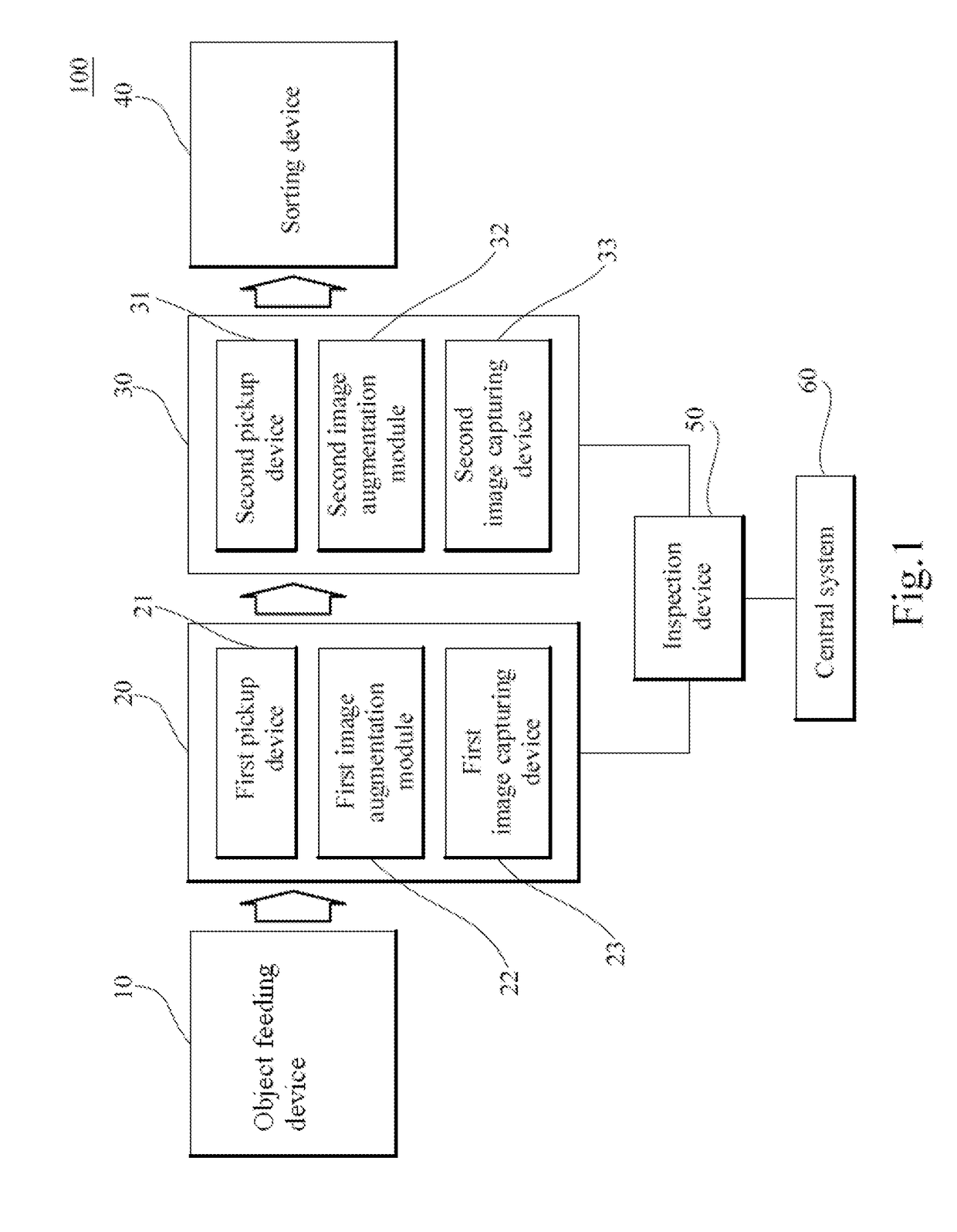
[0037]In the first embodiment, two image augmentation modules (i.e., the first image augmentation module 22 and the second image augmentation module 32) each configured as a curved-surface mirror are disclosed. Each curved-surface mirror has an opening at the center so that the object SP can be placed in the opening. Moreover, each curved-surface mirror can receive light over a wide range of angles and can therefore reflect most of the portion of the object SP that juts out of the opening.

[0038]In a preferred embodiment, the center of the object SP can be moved to the focus of the curved-surface mirror during inspection to increase the reflected area. The inspection procedure corresponding to the first embodiment is detailed below with reference to the multi-view-an...

second embodiment

[0042]FIG. 8 to FIG. 11 show different views of a set of flat mirrors in the image augmentation modules of the present invention.

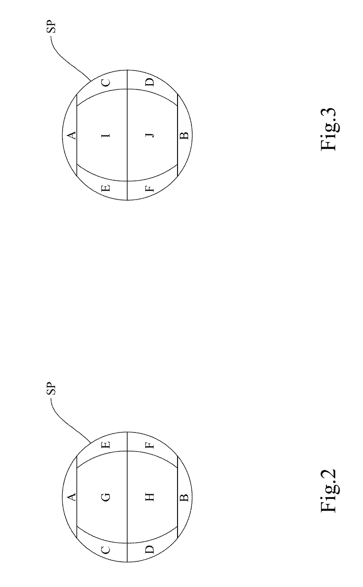
[0043]As shown in FIG. 8 and FIG. 9, flat mirrors W11, W12, W13, and W14 of the first multi-view-angle image capturing device 20 are evenly distributed along the periphery of an opening H1 and extend in four directions respectively. The first pickup device 21 places the object SP into the opening H1 in order for the flat mirrors W11, W12, W13, and W14 to reflect the object SP and thereby form images thereof from four angles respectively. As shown in FIG. 8 and FIG. 9, with the flat mirrors W11, W12, W13, and W14 provided in four directions of the object SP respectively, and with section A (or the upper hemisphere in general) of the object SP facing the first image capturing device 23, section C will be reflected by the flat mirror W11, section G by the flat mirror W12, section E by the flat mirror W13, and section I by the flat mirror W14. The five section...

third embodiment

[0046]the image augmentation modules of the present invention is shown in FIG. 12 to FIG. 15.

[0047]In this embodiment, the image-taking angle of each image capturing device with respect to the object SP is varied by changing the angle of the corresponding flat mirrors E11 and E12, or E21 and E22, with respect to the capturing direction of the image capturing device. As shown in FIG. 12 and FIG. 13, the first pickup device 21 moves the entire object SP through the opening H3 between the flat mirrors E11 and E12 in order for more rear sections of the object SP to be reflected, allowing the front-hemisphere (relatively close to the image capturing device side) and the rear-hemisphere (relatively rear the image capturing device side) of the object SP to be photographed in one take. As each image capturing device can obtain the images of at least two sections of the object SP from one flat mirror, only two flat mirrors are required in this embodiment to obtain the images of five sections...


PUM


Abstract

A multi-view-angle image capturing device for capturing surface images of a object comprising a pickup device, an image augmentation module, an image capturing device, and an inspection device. The pickup device loads the object to an inspection position. The image augmentation module is configured around the inspection position so as to reflect different view angle images of the object. The image capturing device is positioned at the inspection position and captures images of the object and images reflected by the image augmentation module so as to obtain a plurality of view angle images of the object. The inspection device receives the plurality of the view angle images of the object so as to inspect surface of the object.

Description

BACKGROUND OF THE INVENTION1. Technical Field[0001]The present invention relates to a multi-view-angle image capturing device and a multi-view-angle image inspection apparatus thereof more particularly to a multi-view-angle image capturing device and a multi-view-angle image inspection apparatus thereof for obtaining a plurality of view angle images of objects in a single shot.2. Description of the Prior Art[0002]Automated Optical Inspection (AOI) is an inspection technique using mechanical vision to improve the error of the traditional inspection technique that uses manpower to operate the optical instrument. The application filed of AOI includes research development of high-tech industry, manufacturing quality control, national defense, daily commodities, health care, environmental protection, electricity and others.[0003]Image processing technology is applied to newspaper industry in early years and gradually applied to other filed lately. At present, the mechanical vision has be...

Claims


Application Information

Patent Timeline
IPC IPC(8): G06T5/50G06T7/00
CPCH04N13/351G06T7/0002G06T5/50G01N21/8851G01N2021/8854H04N23/50G02B13/06G01N21/8806G01N21/9515G01N2021/8887G01N21/951
Inventor CHANG, HSUN-HAOCHEN, YEN-SONG
Owner UTECHZONE CO LTD
Why Eureka
Try Eureka