Cooking method

a technology of cooking method and cooking liquid, which is applied in the field of cooking method, can solve the problems of non-uniform heating of cooking ingredients, inability to effectively stir-fry the core part of accumulated ingredients, and failure to eliminate the accumulation of ingredients, etc., and achieve the effect of rapid and uniform heating of cooking ingredients

Inactive Publication Date: 2018-06-28
HUA XIAOLING
View PDF4 Cites 7 Cited by
  • Summary
  • Abstract
  • Description
  • Claims
  • Application Information

AI Technical Summary

Benefits of technology

[0008]It is, therefore, one of the objectives of the present invention, to solve the above drawbacks in the prior art, to provide a cooking method, which can not only rapidly and uniformly heat up cooking ingredients, but also effectively improve stir-flying effects.

Problems solved by technology

In the course of using the above cooking apparatus, as shown in FIG. 12, the cooking ingredients 30′ are largely deposited on the bottom of the pot 30, and although a stir-frying mechanism is arranged to stir the cooking ingredients so that ingredients at different positions in the pot and different surfaces of the ingredients are more likely to be in contact with the pot body, it still fails to eliminate the accumulation of the ingredients during stir-flying process, and the core part of the accumulated ingredients cannot be effectively stir-fried.
That is to say, the cooking ingredients can only be heated in a stacked mode, resulting in non-uniform heating of the cooking ingredients and low heating and cooking efficiency.
Moreover, when using a stir-flying mechanism like this for stir-flying, cooking ingredients, subject to large external battering force, are likely to split apart, failing to retain their original shapes and their totality.
This is a great drawback in view of people's strict demand for “shape” in Chinese dishes.
Meanwhile, cooking ingredients are in contact with each other and with the pot body only by a small acting force; with a large heat resistance, heat is hindered from being transferred to cooking ingredients that are far away from the inner wall of the pot body, resulting in the non-uniform heating of the cooking ingredients and low heating and cooking efficiency.
However, such an arrangement is disadvantageous in that the size of the cooking equipment is quite large.

Method used


Image

  • Cooking method
  • Cooking method
  • Cooking method

Examples


embodiment 1

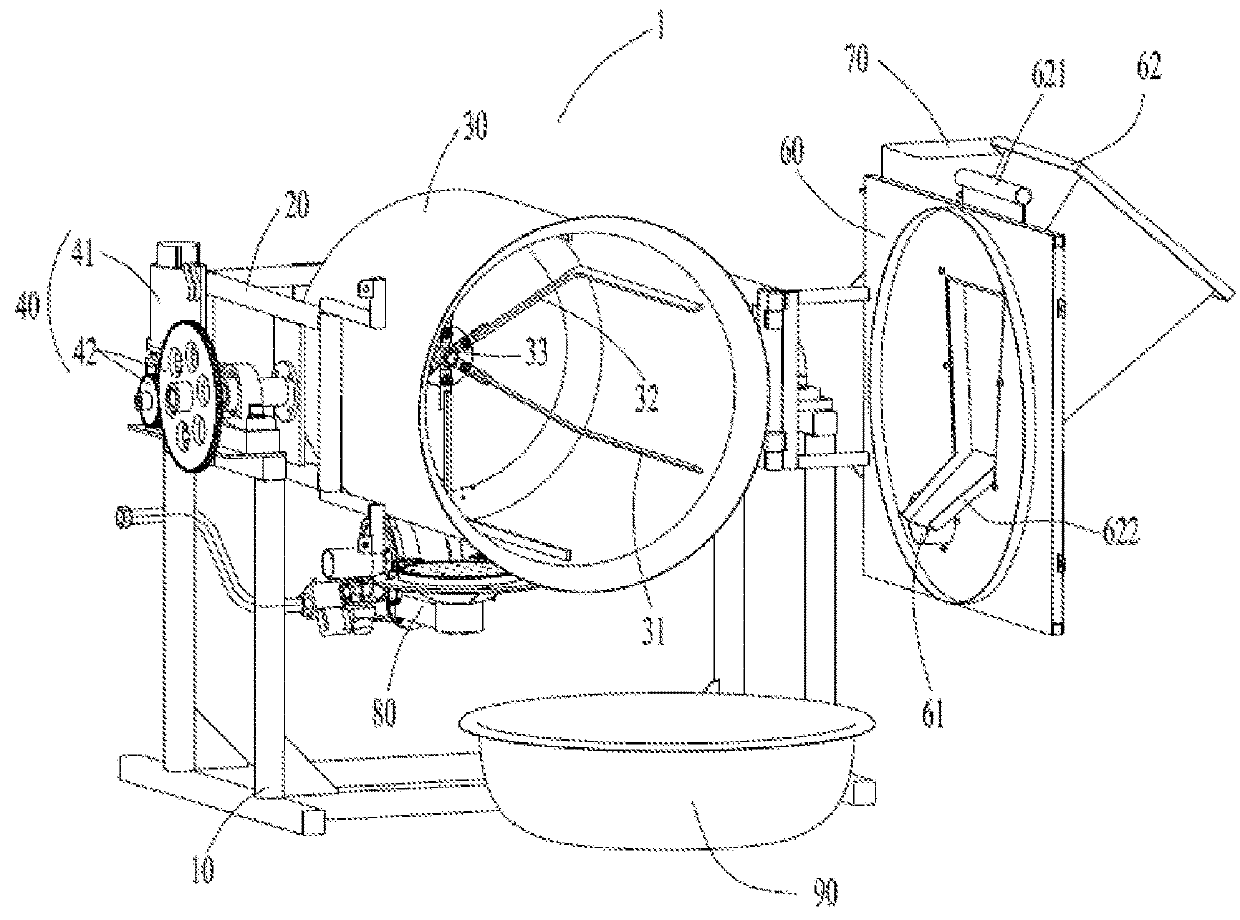
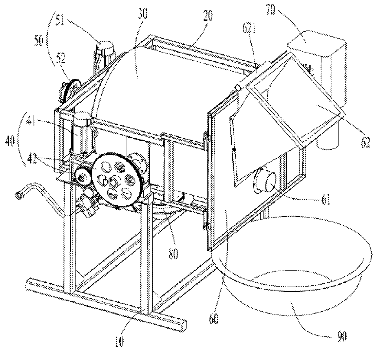
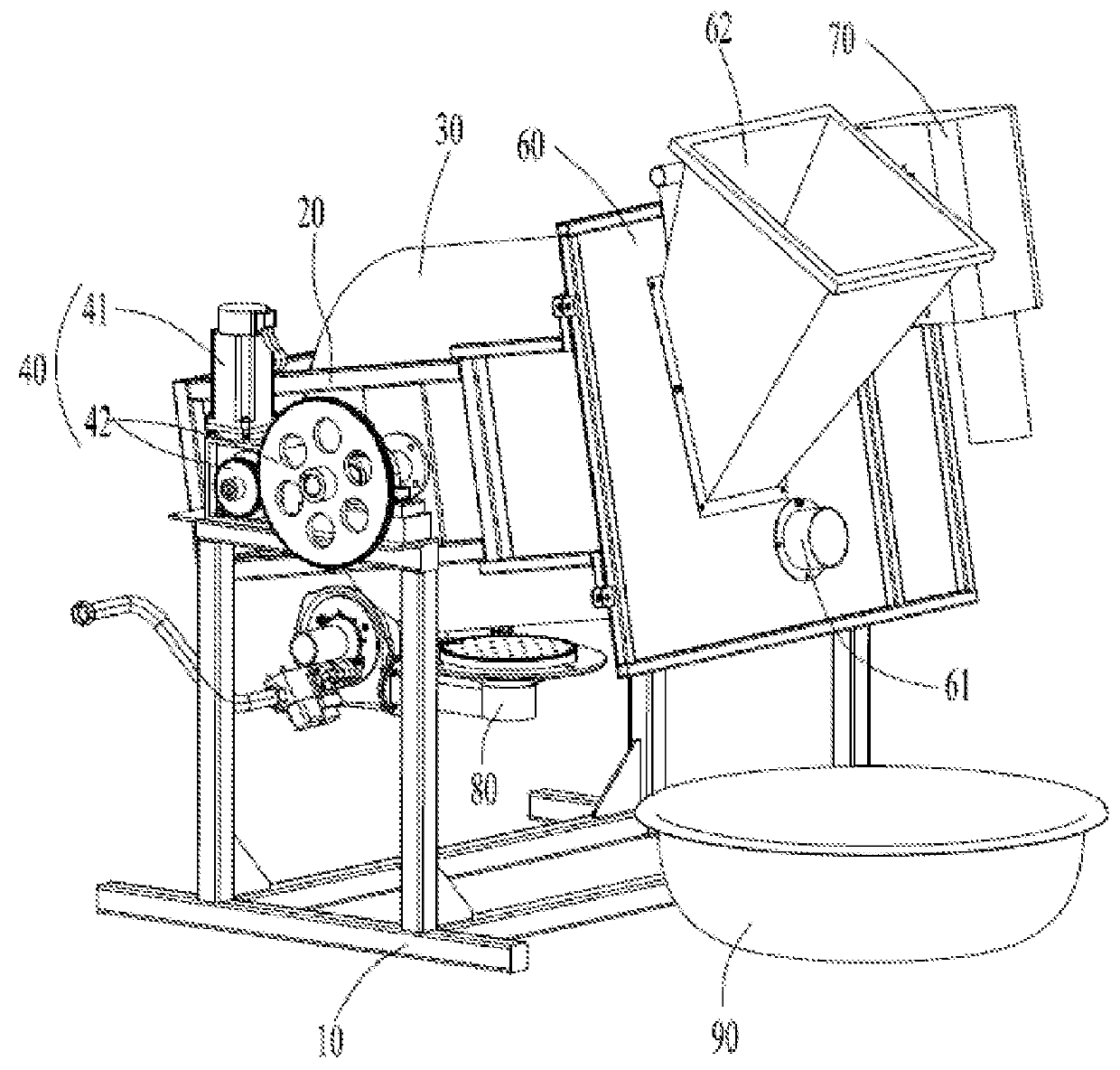
[0064]As shown in FIGS. 1-2, cooking system 1 according to the embodiment comprises an arithmetic processor, an instruction input device and a control device (not shown), a main body support 10, and a pot body support 20 rotatably arranged on the main body support 10, a pot body 30 which is rotatably arranged on the pot body support 20, an angle adjusting device 40 which is arranged on the main body support 20, a rotation driving device 50 which is arranged on the pot body support 20, and a pot cover 60 which is arranged on the pot body support 20 and can be opened and closed, a hot air heating device 70 which is arranged on the pot cover 60, a gas burner 80 which is arranged below the pot body 30 for heating up the pot body 30, and a dish discharging device 90 for unloading the cooked dishes.

[0065]The pot body 30 is barrel-shaped with the inner circumference of its cross section being circular, and the main body of the pot body is provided with an approximately equal inner diameter...

embodiment 2

[0079]As shown in FIG. 6, in this embodiment, a pot body 130 is rotatably arranged on a pot body support 120, a conical feature 131 which is inclined towards the rotating axis of the pot body 130 is formed at one end of the pot body adjacent to the pot opening of the pot body. The rotating shaft of the pot body is connected with a gear transmission mechanism 152, wherein a motor 151 drives the pot body 130 to rotate around the rotating shaft of the pot body 130 through the gear transmission mechanism 152.

[0080]Referring to FIGS. 6 and 7, six ribs 132 annularly arrayed are arranged on the inner wall of the pot body 130, the ribs 132 extend continuously between two longitudinal ends of the pot body 130 in the direction of the rotation axis of the pot body 130. Six scraping members 134 capable of doing reciprocating rectilinear motion along the rotating axis direction of the pot body 130 are arranged in the pot body 130, and each of the scraping members 134 is arranged between every tw...

embodiment 3

[0086]As shown in FIG. 8, in this embodiment, a scraping member 231 which is capable of extending and retracting along the radial direction of the pot body 230 is arranged in the pot body 230. The scraping member 231 extends continuously between the two longitudinal ends of the pot body 230 in the direction of the rotation axis of the pot body 230, and is fixedly connected with a slide bar 232 at the end which is far away from the pot opening.

[0087]The slide bar 232 is slidably mounted on a fixing base 233,which is fixedly installed in the pot body 230. The longitudinal end of the slide bar 232 abuts against a cam 243, and the cam 243 is connected with a gear transmission mechanism 242 through a rotating shaft penetrating through the rotating shaft of the pot body. The motor 241 drives the cam 243 to rotate through the gear transmission mechanism 242, so that the scraping member 231 extends and retracts along the radial direction of the pot body 230. When extended, the scraping memb...


PUM


Abstract

The present invention provides a cooking method, comprising the following steps:
    • (1) feeding cooking ingredients into a barrel-shaped pot body;
    • (2) controlling the pot body to rotate at a first rotating speed which is lower than a critical rotating speed and which enables cooking ingredients to, driven by the pot body, rotatingly ascend and then fall down; wherein the cooking ingredients are controlled to rotate, along with the pot body
    • (3) controlling the pot body to rotate at a second rotating speed which is greater than or equal to a critical rotating speed, enabling cooking ingredients to attach to the pot body and rotate along with the pot body and then fall down.
The cooking method of the present invention not only achieves rapid and uniform heating of cooking ingredients, but also effectively improves cooking productivity.

Description

FIELD OF THE INVENTION[0001]The present invention relates to a cooking method; more particularly, the present invention relates to a cooking method for cooking dishes.BACKGROUND OF THE INVENTION[0002]Stir-flying is a process of flying cooking ingredients in the pot, generally featuring quick stirring of the ingredients in the heated pot, so that they are rapidly and uniformly heated, thereby producing crisp, tender, fresh and fragrant dishes. In the art some automatic or semi-automatic cooking systems are developed to replace or reduce manual labors in cooking.[0003]Chinese Patent No. 200810029877.8 discloses a cooking equipment comprising a body bracket, a pot disposed on the body bracket, a rotation mechanism and a turning-over mechanism in which the pot is in shape of a barrel, a hemisphere or the like with an opening at its end, and with a stirring mechanism installed inside the pot. The rotation mechanism is connected to the pot body to drive the pot to rotate around a rotation...

Claims


Application Information

Patent Timeline
Patent Type & Authority Applications(United States)
IPC IPC(8): A47J43/07A47J27/00
CPCA47J43/07A47J27/002A47J37/106
Inventor HUA, XIAOLING
Owner HUA XIAOLING
Why Eureka
Try Eureka