[0032]Examples of embodiments are described below with the aid of the figures. In the figures, elements which are identical or similar, or have identical effects, are designated with identical reference signs, and in order to avoid redundancy repeated description of these elements is in part dispensed with.
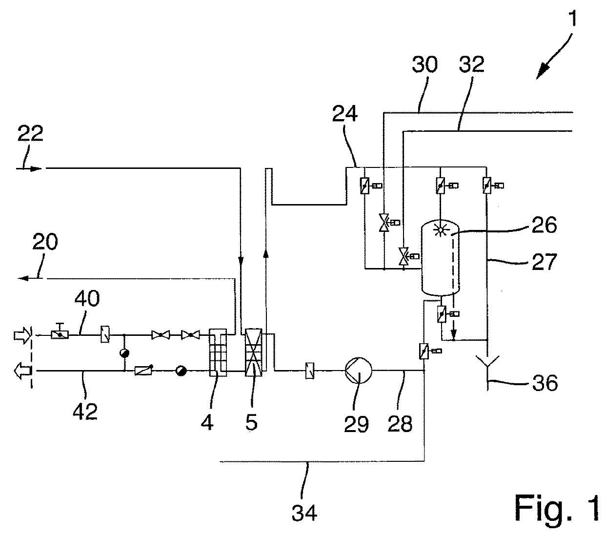
[0033]FIG. 1 shows schematically a device 1 for cleaning a plant part that is to be cleaned in a beverage filling plant. The cleaning of the parts of the plant takes place by means of cleaning media, which are conveyed to the part of the plant that is to be cleaned via a medium inflow 20, and away from the part of the plant that is to be cleaned via a medium return flow 22. The cleaning media can thereby be conveyed in a cycle.
[0034]In order to clean the exterior of the part of the plant that is to be cleaned, the medium inflow 20 discharges, for example, into exterior cleaning nozzles or flood nozzles, by means of which the cleaning medium that is supplied via the medium inflow 20 is applied to the surfaces that are to be cleaned of the part of the plant that is to be cleaned. The medium inflow 20 can, however, also be introduced into a closed area of the part of the plant that is to be cleaned, for example into the product lines and other medium lines, in order to perform an interior cleaning of the parts of the plant that are to be cleaned. In this case, the cleaning medium can in particular be used in a CIP cleaning. The supplying of cleaning media for either external cleaning or internal cleaning of plant parts in beverage filling plants is known in principle.
[0035]After it has completed flowing through the plant part that is to be cleaned, or completed flowing over the surfaces to be cleaned, the used cleaning medium is returned via the medium return flow 22.
[0036]In the case of exterior cleaning, the used cleaning medium reaches the medium return flow 22 for example by means of the collection of the cleaning medium flowing off of the surfaces at one or more runoff points of the plant part that is to be cleaned. For this, a floor plate or equipment table which provides suitable outflows is usually provided in the floor area of the plant part that is to be cleaned. The floor area can for example also be designed as a funnel-shaped floor, which collects all media that run off at a single outflow point and discharges these media into the medium return flow 22.
[0037]In the case of interior cleaning of the plant part that is to be cleaned, it can similarly be provided that the used cleaning medium is removed via the floor area of the plant part that is to be cleaned, for example if the cleaning medium, after flowing through the filling product path, flows out of the filling valves and is similarly collected in the floor area of the floor area of the plant part that is to be cleaned. In the case of interior cleaning also, the cleaning medium can have a closed cycle, in which the used cleaning medium is returned in a cycle via suitable cleaning channels, which are also referred to as CIP channels, and conveyed to the medium return flow 22.
[0038]The cleaning medium that is supplied via the medium inflow 20 and returned via the medium return flow 22 can be conveyed in a cycle in the device 1, wherein a circulation line 24 is provided to convey the cleaning medium from the medium return flow 22 to a buffer tank 26. From the buffer tank 26, the cleaning medium is again conveyed to the medium inflow 20, via a supply line 28 which also includes a pump 29.
[0039]In order to enable differing cleaning media to be provided, and the cleaning medium that is conveyed in a cycle to be regenerated, for example the supply of an acid concentrate is provided via an acid supply line 30 and the supply of a lye concentrate is provided via a lye supply line 32. Accordingly, in order to produce or maintain a desired concentration of lye or acid, the concentrate can be conveyed via the lye supply line 32 or the acid supply line 30 respectively to the cleaning medium that is accommodated in the buffer tank 26. In this case, the desired concentration can be monitored by sensors provided in the circulation line 24, which control the supply of acid or lye by means of a suitable feedback control.
[0040]Fresh water can be fed into the system via a fresh water connection 34. The fresh water connection 34 thereby enables fresh water to be supplied, in order either to achieve the replacement of a first cleaning medium with a second cleaning medium, or to compensate for the loss of cleaning medium due to the cleaning itself and the evaporation of cleaning medium.
[0041]The cleaning medium, which is accommodated in the buffer tank 26, or prepared or treated in the buffer tank 26, can be removed from the device 1 via a drainage connection 36.
[0042]The cleaning medium can be conveyed past the buffer tank 26 via a bypass 27. This is particularly advantageous if clear water is used as the cleaning medium, and for example it is used for a pre-rinse immediately after production, or is used for intermediate rinsing or post-rinsing. The water does not need to be stored in the interim in the buffer tank 26. In the case of the pre-rinse, in which a significant portion of filling product remains to be transported with the pre-rinse water, the cleaning medium can also be conveyed via the bypass 27 directly to the drainage connection 36, and discarded.
[0043]Accordingly, for example in order to carry out a preliminary cleaning, a cleaning medium in the form of fresh water can be introduced into the medium inflow 20 via the fresh water connection 34, the part of the plant that is to be cleaned can be cleaned with the fresh water, and the cleaning medium can then be conveyed via the medium return flow 22 and the bypass 27 directly to the drainage connection 36. No recirculation thereby takes place.
[0044]For a subsequent cleaning of the parts of the plant that need to be cleaned, either lye supplied via the lye supply line 32, or acid supplied via the acid supply line 30, is added to the fresh water supplied via the fresh water connection 34, in order thereby to provide the cleaning medium with the applicable acid or lye concentrates. The cleaning media can then be stored temporarily, by means of the buffer tank 26, for cleaning and in order to provide a suitable exposure time, and recirculated by means of the pump 29. During the cleaning phase, the chemical composition is constantly checked, and if necessary readjusted by the introduction of additional fresh water or by the adding of acid or lye concentrates.
[0045]In the cleaning of parts of the plant that are to be cleaned, the important factors are not only the composition of the chemicals and the mechanical application of cleaning impulses, but also a third factor, the temperature. Because of this, the cleaning medium is heated by means of a heating unit 4.
[0046]The heating unit 4 is provided in the medium inflow 20, such that the cleaning medium, which is supplied via the medium inflow 20 to the plant parts that are to be cleaned, is brought to the intended temperature by means of the heating unit 4. In the example embodiment that is shown, the heating unit 4 is provided in the form of a heat exchanger, which is supplied with process steam via a steam line 40. The condensate is returned via a condensate line 42. In the heating unit 4, which is provided as a steam heat exchanger, the cleaning medium that is supplied to the medium inflow 20 can be brought to the target temperature. For this purpose, a temperature sensor, by means of which the heat output of the heat exchanger can be regulated, can be provided downstream of the heating unit 4.
[0047]In addition, a recuperator 5 is provided in the medium inflow 20 upstream of the heating unit 4. The cleaning medium that is to be conveyed to the heating unit 4 flows through the recuperator 5. In other words, the recuperator 5 is disposed in the medium inflow 20, and cleaning medium that is to be conveyed to the part of the plant that is to be cleaned flows through it before entering the heating unit 4. The cleaning medium in the medium inflow 20 is conveyed into a first chamber system of the recuperator 5.
[0048]Cleaning medium that is returned via the medium return flow 22 flows through the second chamber system of the recuperator 5. By this means, at least a significant portion of the heat energy that is present in the cleaning medium that is returned via the medium return flow 22 can be transferred to the cleaning medium that flows through the medium inflow 20, before the cleaning medium flows through the heating unit 4. Thus by means of the recuperator 5 the cleaning medium can be pre-heated before it flows into the heating unit 4.
[0049]By this means it possible to reduce the required heat output of the heating unit 4 that is needed to reach the target temperature of the cleaning medium in the medium inflow 20. By the use of the recuperator 5, it is thereby also possible to reduce the maximum energy that needs to be transferred by means of the heating unit 4 to the cleaning medium in the medium inflow 20. It is thereby possible to reduce, for example, the load on the steam network of the beverage filling plant.
[0050]If a lost cleaning method is used, in which the cleaning medium is removed via the drainage connection 36, it is particularly advantageous that the heat energy that is still present in the discarded cleaning medium is transferred, to a substantial extent, to the new cleaning medium, before the new cleaning medium, which is now pre-heated, is heated to its target temperature in the heating unit 4.
[0051]The effect can be particularly well understood by means of the example of post-rinsing following the completion of chemical cleaning. In particular, fresh water for post-rinsing is introduced into the supply line 28 via the fresh water connection 34, then pumped via the pump 29 through the recuperator 5, and then heated to the target temperature by means of the heating unit 4. The cleaning medium that is still in the cleaning system from the previous cleaning step, for example, is at a higher temperature, with the result that the cleaning medium that is returned via the medium return flow 22 raises the fresh water in the recuperator 5 to a first temperature level. Accordingly, the heating performance of the heating unit 4 can be reduced.
[0052]In addition, when a further flow of fresh water is added via the fresh water connection 34, a significant part of the heat energy that is contained in the rinse water that is returned via the medium return flow 22 can be transferred to the fresh water.
[0053]Furthermore, the discarded cleaning medium which is guided into the drainage connection 36 has lost some of its heat after flowing through the recuperator 5, so that an excessive thermal load on the waste water network is avoided.
[0054]As a result, the overall heating performance of the heating unit 4 can be reduced, particularly when the parts of the plant that are to be cleaned are post-rinsed, in which case it is advantageous to post-rinse with very hot water in order to achieve rapid drying of the parts of the plant that have been rinsed. It is also possible by this means to reduce the quantity of steam which needs to be supplied via the steam line 40.
[0055]In FIG. 2, a dash-dot curve shows schematically the consumption over time of steam for a heating unit according to the state of the art, which operates without the use of a recuperator.
[0056]By way of contrast, the solid line shows the consumption over time of steam for the heating unit 4 of the present design, with the use of the recuperator 5. It is immediately clear that the maximum consumption of steam from the steam network is significantly reduced, with the result that a peak load on the steam network can be reduced. In this manner it can be achieved that the dimensions of a steam generator for a steam network of the plant can be reduced, so that the beverage filling plant as a whole can thereby be designed more efficiently.
[0057]To the extent applicable, all individual features described in the example embodiments can be combined with each other and/or exchanged, without departing from the field of the invention.