
A plough system

a technology of a plough and a chuck is applied in the field of plough systems, which can solve the problems of uneven surface, unfavorable total economic crop yield, and inability to achieve the effect of optimum total economic crop yield

Inactive Publication Date: 2018-07-12
AGRO INTELLIGENCE APS
View PDF14 Cites 1 Cited by
  • Summary
  • Abstract
  • Description
  • Claims
  • Application Information

AI Technical Summary

Benefits of technology

The invention improves growing conditions for crops seeds by controlling the soil level during ploughing and ensuring even growth. It also makes ploughing more efficient by avoiding the need to plough certain areas twice.

Problems solved by technology

Although this way of performing the ploughing has proven efficient, there are however some drawback using this technique.
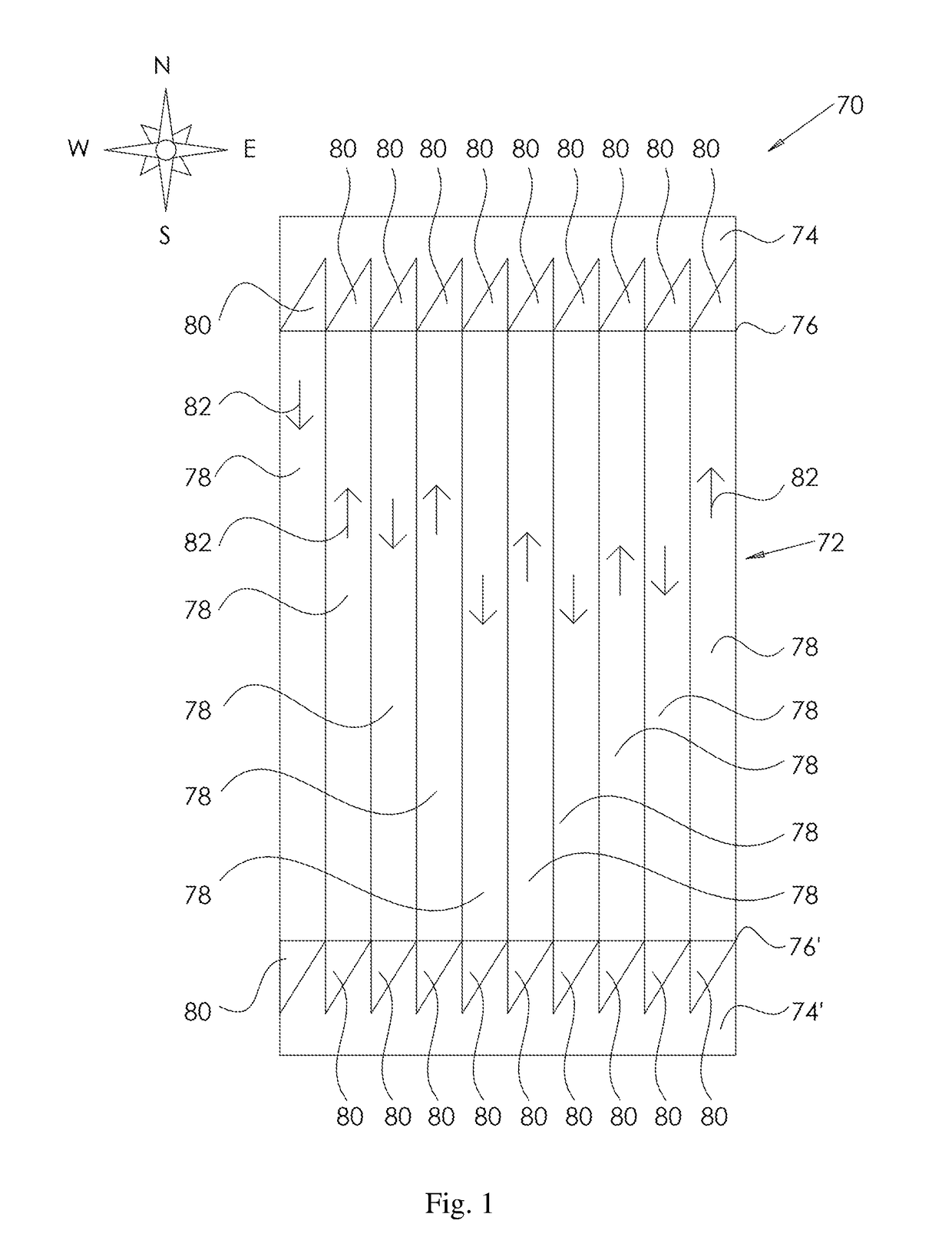
One drawback is, that due to the fact that all the plough shears are arranged in a staggered configuration which is not perpendicular to the direction of movement of the plough through the soil, it will not be possible, at the boundary between the inner, main part of the field and the headland to exactly and precisely plough the soil up to this boundary.
This obviously has the consequence that the crop seeds to be sown will encounter so much competition from the weed that has been turned around twice, that the growth conditions for these seeds and hence the total economical crop yield will be far from optimum.
Additionally, the overlap will result in an uneven surface after ploughing, while the boundary of the ploughing of the main land conflicts with the following ploughing of the headland.
Furthermore, ploughing the headland will due to ploughing the soil twice result in a situation, where crop residues at least partly will not be covered by soil.

Method used


Image

  • A plough system
  • A plough system
  • A plough system

Examples


Embodiment Construction

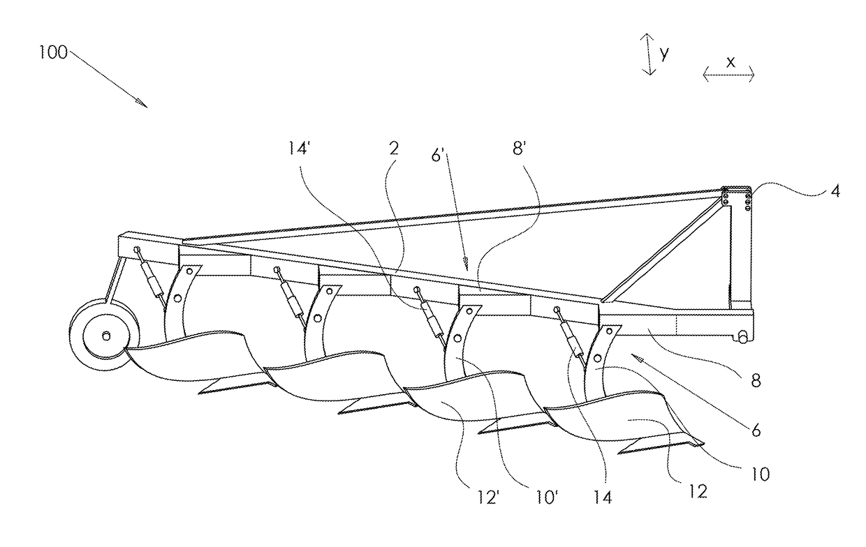
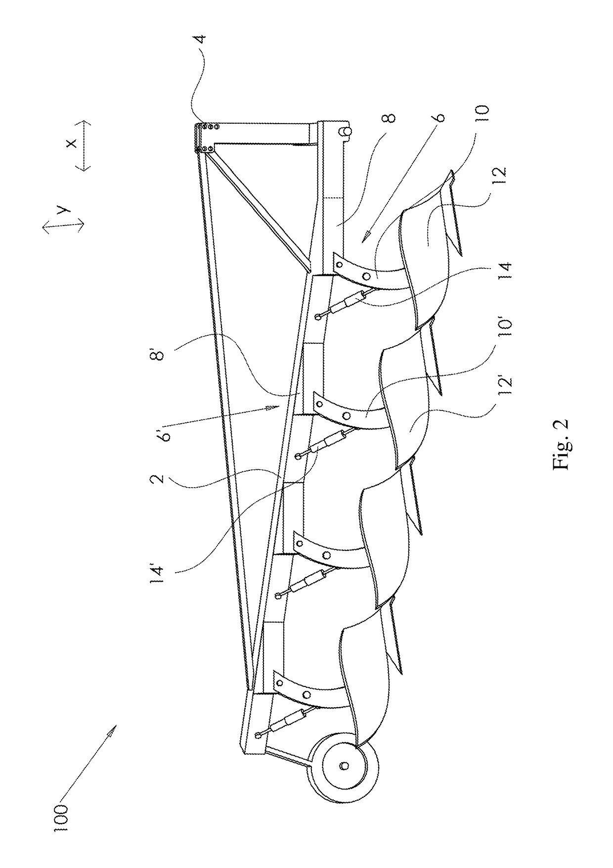
[0042]The present invention relates in a first aspect to a plough system comprising:

[0043]i) a plough frame, said plough frame comprising coupling means for coupling said plough frame to a towing vehicle;[0044]wherein said plough frame having an extension in a lengthwise direction, and an extension transverse direction;[0045]wherein said plow frame comprising two or more lifting means; said lifting means comprising a fixed part being mounted on said plough frame, and a moving part carrying a plough shear;[0046]wherein each said lifting means comprising an actuator;[0047]wherein said actuator being configured to allow altering of said plough shear from a lowered position to a raised position, and vice versa;[0048]wherein said plough shears being arranged on said frame in mutual staggered orientation in relation to a lengthwise direction as well as to a transverse direction;

[0049]ii) a control unit configured to receive controlling input, and in response thereto independently activate...


PUM


Abstract

The present invention relates to a plough system (100) comprising: i) a plough frame (2), said plough frame comprising coupling means (4) for coupling said plough frame to a towing vehicle; wherein said plough frame having an extension in a lengthwise direction (X), and an extension in a transverse direction (Y); wherein said plough frame comprising two or more lifting means (6,6′); said lifting means comprising a fixed part (8) being mounted on said plough frame (2), and a moving part (10) carrying a plough shear (12, 12′); wherein each said lifting means (6,6′) comprising an actuator (14, 14′); wherein said actuator being configured to allow altering of said plough shears (12, 12′) from a lowered position to a raised position, and vice versa; wherein said plough shears (12,12′) being arranged on said frame in mutual staggered orientation in relation to a lengthwise direction as well as to a transverse direction; ii) a control unit (16) configured to receive controlling input (18), and in response thereto independently activate one or more actuators (14, 14′) associated with said lifting means; thereby enabling independent raising and / or lowering of one or more of said plough shears (12,12′). The plough system provides improved ploughing quality of fields of soil comprising a mainland and a headland.

Description

FIELD OF THE INVENTION[0001]The present invention relates in a first aspect to a plough system for ploughing soil. The present invention relates in a second aspect to the use of a plough system of the first aspect for ploughing soil. The present invention relates in a third aspect to a method of ploughing.BACKGROUND OF THE INVENTION[0002]Within the field of agriculture ploughing has been around a long time as an effective tillage method.[0003]Ploughing is used as a way to prepare the soil for seeding. When ploughing the soil is turned around, so that soil previously located in a certain depth will appear as a top layer of the soil. A typical ploughing depth is 18 to 20 cm, but can vary between 5 and 100 cm.[0004]The turning of the soil upon ploughing will provide for aerating the soil and in this way will provide mineralization of soil and better drainage of water which improve fertility. Also, ploughing will remove residues of last year's crops as well as removal of any weed presen...

Claims


Application Information

Patent Timeline
IPC IPC(8): A01B3/36A01B63/00A01B69/00
CPCA01B3/36A01B63/008A01B69/003A01B69/008
Inventor GREEN, OLENIELSEN, SOREN KIRKEGAARD
Owner AGRO INTELLIGENCE APS
Learn More