Water Draining Structure of Dehumidifier And Dehumidifier

a technology of dehumidifier and water draining mechanism, which is applied in the field of household appliances, can solve the problems of increasing the risk of water leakage, preventing fire, and damage to the electromagnet pump, so as to reduce the risk of leakage, the effect of fully utilizing the drainage capacity of the pump and eliminating the pressure loss due to the connection of the pip

Active Publication Date: 2018-07-12
JIANGSU YOAU ELECTRIC CO LTD
View PDF6 Cites 6 Cited by
  • Summary
  • Abstract
  • Description
  • Claims
  • Application Information

AI Technical Summary

Benefits of technology

[0019]Advantages of the invention are: the invention provides a water draining mechanism of a dehumidifier, comprising a water receiving tray receiving condensed water of the dehumidifier. The water receiving tray comprises a water tank outlet, a main water outlet arranged outside the casing of the dehumidifier as a whole, the main water outlet being arranged opposite the water tank outlet; a pump used for draining is provided on the bottom of the outside of the water receiving tray, the pump being directly connected with the water receiving tray, eliminating the need of providing a pipe to connect with the dehumidifier pump, therefore reducing the risk of leaking. By connecting the pump with the water receiving tray directly, the pressure loss due to the connection of pipe is eliminated, the drainage capacity of the pump is utilized fully. Without installing or detaching additional pipes during installment or maintenance, operation is easier.
[0020]The pump uses a low voltage DC diaphragm type pump driven by a power source of 12V, enabling the drainage lift over 10 meters without risking overheating; and the DC diaphragm type pump generates pressure difference and drain water by the reciprocating motion of the diaphragm inside, noise is very low; arranging the pump vertically at the bottom of the water receiving tray not only provide isolation of the pump from the water receiving tray, the water tank and other water receiving pieces, improving safety, but help mitigating vibration of the pump without providing specific damper. Rubber rings made of rubber are applied between the pump and the water receiving tray, therefore enhancing seal performance and security. Also, the installation is more solid by fixing the pump on the bottom of the outside of the water receiving tray by screws.

Problems solved by technology

As error or aging occur, the electromagnetic pump will be damaged or even catch fire due to heating up of the pump.
But in this application, the pump still needs to be connected with inlet pipes and outlet pipes, bringing increased risk of water leaking; the pipes are connected with the pump in a clamping manner, making it harder to operate and causing loose installation; installation space and gaps are reserved for a plurality of fireproof panels around the pump, much space are occupied; further, using fireproof panel can only prevent catching fire instead of being heated and self-igniting.
The pump is arranged inside the water tank, it is dangerous because the pump is an electrical piece; further, the pump is installed by a frame, also requiring connecting with outlets and therefore increase the risk of water leaking; the structure thereof is rather complicated, making it inconvenient to operate during the maintenance; while using brushless DC pump can reduce noise, high-speed impellers are needed to drain water, noise caused by impaction on high-speed impellers of water is unavoidable

Method used


Image

  • Water Draining Structure of Dehumidifier And Dehumidifier
  • Water Draining Structure of Dehumidifier And Dehumidifier
  • Water Draining Structure of Dehumidifier And Dehumidifier

Examples


example 1

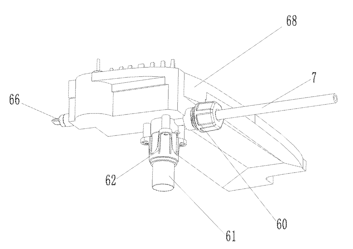
[0030]A water draining mechanism of a dehumidifier, comprises a water receiving tray 64 receiving condensed water of the dehumidifier, the water receiving tray 64 comprising a water tank outlet 65, a main water outlet 60 arranged outside the casing of the dehumidifier as a whole, the main water outlet 60 being arranged opposite the water tank outlet 65; a pump 61 used for draining is provided on the bottom of the outside of the water receiving tray 64, and the pump 61 is directly connected with the water receiving tray 64. The pump 31 is a DC diaphragm type pump driven by a 12V power source, and the pump 31 is mounted vertically at the bottom of the water receiving tray 64.

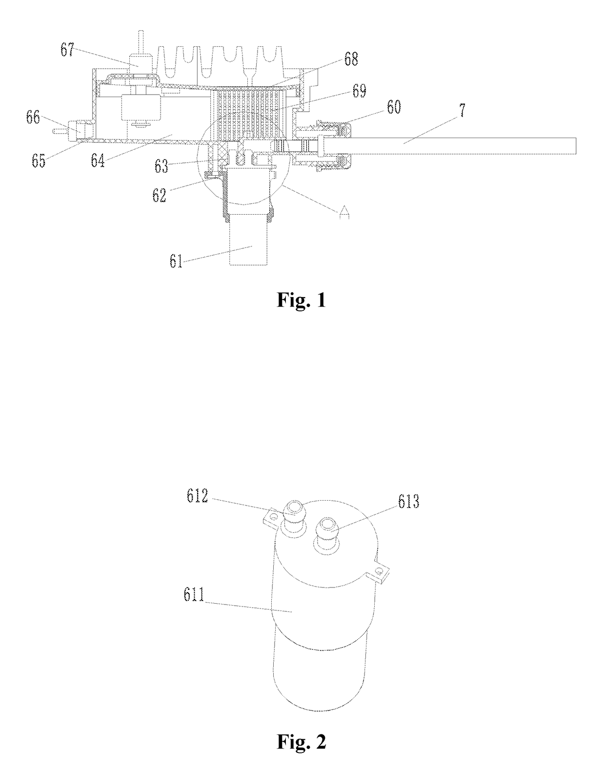
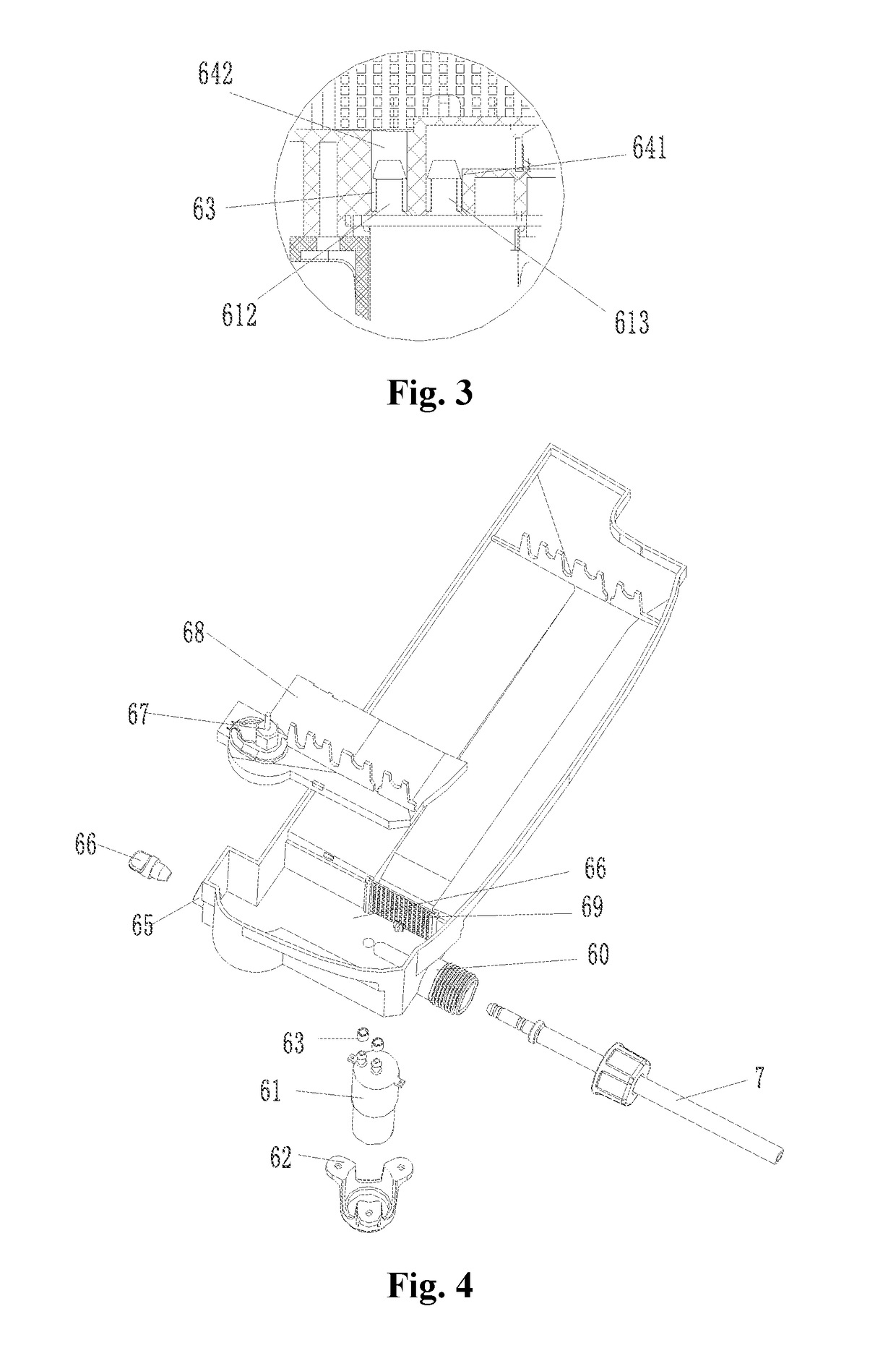
[0031]The pump 31 comprises a pump body 611, a pump inlet 612, and a pump outlet 613, and the pump inlet 612 and the pump outlet 613 are on the same end of the pump body 611, the water receiving tray 64 is provided with a tray outlet 642 connected directly with the pump inlet 612 and a tray inlet 641 connected dir...

example 2

[0032]Like Example 1, further, an installation seat 62 used for securing the pump 31 is included, and the installation seat 62 is fixed at the bottom of the water receiving tray 64 by screw. Sealing rings 63 used for sealing are provided on the joint of the pump inlet 612 and the tray outlet 642 and the joint of the pump outlet 613 and the tray inlet 641 respectively; the sealing rings 63 are made of rubber, and a tray cover 68 covering the water receiving tray 64 is arranged above the water receiving tray 64; the tray cover 68 is provided with a water level switch 67 collecting and judging the water level inside the water receiving tray 64 and controlling the drainage of the pump 61 within the predefined water level, and a filter screen 69 is arranged between the tray cover 68 and the water receiving tray 64 and at the inlet of condensed water, and meshes of the filter screen 69 have a size less than 4 mm preferably, and the water tank outlet 65 is provided with a removable plug 66...


PUM


Abstract

A dehumidifier has a water receiving tray receiving condensed water of the dehumidifier. The water receiving tray comprises a water tank outlet, a main water outlet arranged outside the casing of the dehumidifier as a whole, the main water outlet being arranged opposite the water tank outlet; a pump used for draining is provided on the bottom of the outside of the water receiving tray, the pump being directly connected with the water receiving tray, eliminating the need of providing a pipe to connect with the dehumidifier pump, therefore reducing the risk of leaking. By connecting the pump with the water receiving tray directly, the pressure loss due to the connection of pipe is eliminated; the drainage capacity of the pump is utilized fully. Without installing or detaching additional pipes during installment or maintenance, operation is easier.

Description

TECHNICAL FIELD[0001]The invention relates to the field of household appliances, particularly to a water draining mechanism of a dehumidifier and a dehumidifier containing such a mechanism.BACKGROUND[0002]At present, most of dehumidifiers with pump are equipped with AC electromagnetic pumps driven by commercial power. These dehumidifiers are mostly used in basements and need to be provided with a pipe as long as 10 meters or more. To meet the drainage lift of the pump, choosing the electromagnetic pump with high-voltage results in increase of power. As error or aging occur, the electromagnetic pump will be damaged or even catch fire due to heating up of the pump.[0003]In CN201210274227.6, in order to solve the problem of pump catching fire, a dehumidifier provided with a pump inside uses a fireproof panel to control the risk of water leaking and catching fire. But in this application, the pump still needs to be connected with inlet pipes and outlet pipes, bringing increased risk of ...

Claims


Application Information

Patent Timeline
Patent Type & Authority Applications(United States)
IPC IPC(8): F24F13/22B01D53/26F25B13/00F25D21/14F24F3/14F04B43/04
CPCF24F13/222B01D53/265F25B13/00F24F2013/227F24F3/14F04B43/04F24F2003/1446F25D21/14F04B17/03F28F17/005
Inventor HOU, CHENGCAILU, JUN
Owner JIANGSU YOAU ELECTRIC CO LTD
Why Eureka
Try Eureka