Optical fiber and method and apparatus for accurate fiber optic sensing under multiple stimuli

a fiber optic and multiple stimuli technology, applied in the field of optical fibers, can solve the problems of cross-sensitivity, generating sensor measurement errors, and unable to distinguish between temperature and strain, and achieve the effect of reducing or minimizing twist measurement errors

Active Publication Date: 2018-07-12
LUNA INNOVATIONS
View PDF4 Cites 20 Cited by
  • Summary
  • Abstract
  • Description
  • Claims
  • Application Information

AI Technical Summary

Benefits of technology

[0021]Example embodiments minimize or reduce a twist measurement error resulting from difference

Problems solved by technology

Existing Rayleigh or Bragg scattering-based sensors cannot distinguish the difference between temperature and strain.
In practical applications, this cross-sensitivity between temperature and strain can generate errors in the sensor's measurement.
In more complicated sensors, such as those designed to measure shape and position, this cross-sensitivity also contributes to error in the sensor's measured output.
However, the shape sensing systems described in the above patents do not distinguish between temp

Method used


Image

  • Optical fiber and method and apparatus for accurate fiber optic sensing under multiple stimuli
  • Optical fiber and method and apparatus for accurate fiber optic sensing under multiple stimuli
  • Optical fiber and method and apparatus for accurate fiber optic sensing under multiple stimuli

Examples


example implementation

of Strain and / or Temperature Sensor

[0084]The strains referred to in Equation 3 may stem from a variety of physical mechanisms. U.S. Pat. No. 8,773,650 describes strain on a core in a multicore fiber arising from three physical sources: strain applied along the axis of the fiber, strain due to fiber bending, and strain due to an applied twist. The core strain response to applied twist rate given by applied twist angle θ applied over length L is dependent on the core radius to the central axis r and the fiber's intrinsic twist period p, and to first order is given by the expression:

stwist≈Zπr2pp2+(2πr)2θL(5)

Transfer of fiber axial strain εz to the core is dependent on the core radius r, the intrinsic twist period p, and the fiber material's Poisson ratio η, and to first order is given by the expression:

stension≈p2-(2πr)2ηp2+(2πr)2ɛz(6)

The core strain in response to bending is dependent on the core radius r, intrinsic twist period p, the fiber material's Poisson ratio η, the curvature ...

example application

to Shape Sensors

[0091]The following shape sensing fiber description is provided as a specific example of adding an additional measurement core having different optical properties. In the canonical shape sensing calculation, the computation of axial strain / temperature εz, x and y curvature κx, κy, and twist θ / L is performed using a 4×4 matrix calculation, as shown below. A total of 16 linear scaling terms are used to calculate these outputs from the phase derivative or spectral shift OFDDR measurements Δvn in each of the four sensing cores.

(Δv0Δv1Δv2Δv3)=(M11M12M13M14M21M22M23M24M31M32M23M34M41M42M43M44)(ɛzKxKyθ / L)(9)

[0092]In an example shape sensing embodiment, a differently-doped core is included in the fiber (e.g., from one of three previously unused cores) and added as a fifth measurement term which is used to distinguish temperature change ΔT from axial strain εz. This example sensing fiber is illustrated in FIGS. 5 and 6A, 6B. Additional scaling terms are added to bring the mat...


PUM


Abstract

An optical fiber includes primary optical core(s) having a first set of properties and secondary optical core(s) having a second set of properties. The primary set of properties includes a first temperature response, and the secondary set of properties includes a second temperature response sufficiently different from the first temperature response to allow a sensing apparatus when coupled to the optical fiber to distinguish between temperature and strain on the optical fiber. A method and apparatus interrogate an optical fiber having one or more primary optical cores with a first temperature response and one or more secondary optical cores with a second temperature response. Interferometric measurement data associated with each primary and secondary optical core are detected when the optical fiber is placed into a sensing position. Compensation parameter(s) is(are) determined to compensate for measurement errors caused by temperature variations along the optical fiber based on a difference between the first temperature response of the primary cores and the second temperature response of the secondary cores. The detected data are compensated using the compensation parameter(s).

Description

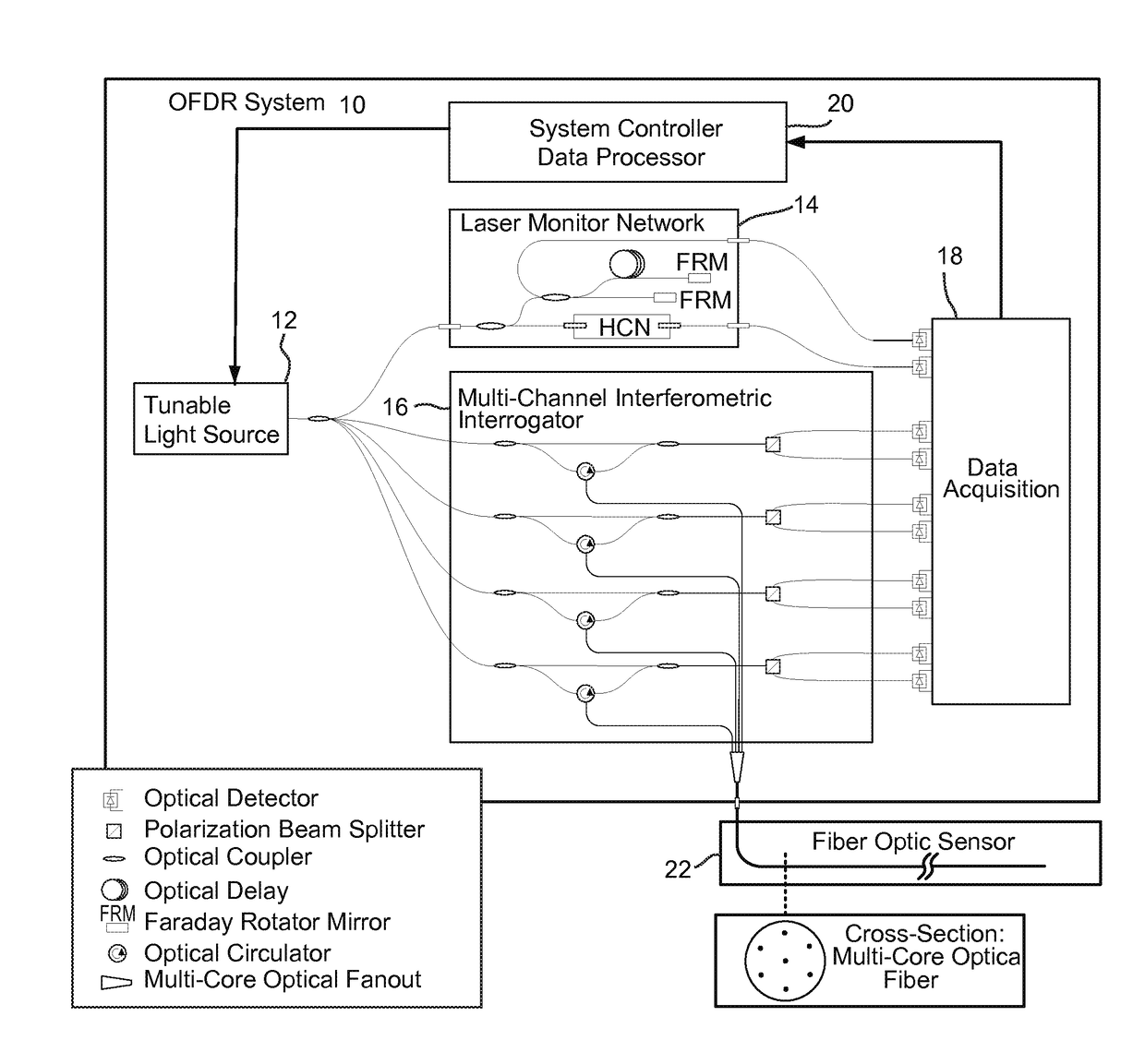
PRIORITY APPLICATION[0001]This application claims priority from U.S. provisional patent application Ser. No. 62 / 077,974, filed on 11 Nov., 2014, the contents of which are incorporated herein by reference.[0002]This invention was made with government support under Contract No. 2014-14071000012 awarded by the IARPA. The government has certain rights in the invention.TECHNICAL FIELD[0003]The technology relates to interferometric sensing applications. One example application is to Optical Frequency Domain Reflectometry (OFDR) sensing using Rayleigh and / or Bragg scatter in optical fiber.BACKGROUND AND SUMMARY[0004]Optical Frequency Domain Reflectometry (OFDR) is an effective technique for extracting external sensory information from the response of an optical fiber. See, e.g., U.S. Pat. Nos. 6,545,760; 6,566,648; 5,798,521; and 7,538,883. OFDR systems rely on scattering mechanisms, such as Rayleigh or Bragg scatter, to monitor phenomena that change the time-of-flight delay (“delay”) or s...

Claims


Application Information

Patent Timeline
IPC IPC(8): G01B11/16G01D5/353
CPCG01B11/16G01D5/35303G01D5/35316G01D5/35361G02B6/02042G01M11/3172G01L1/242
Inventor REAVES, MATTHEW T.RIFE, BRIAN M.LALLY, EVAN M.KREGER, STEPHEN T.
Owner LUNA INNOVATIONS
Why Eureka
Try Eureka