
Method for checking a geometric characteristic and an optical characteristic of a trimmed ophthalmic lens and associated device

Active Publication Date: 2018-07-12
ESSILOR INT CIE GEN DOPTIQUE
View PDF12 Cites 6 Cited by
  • Summary
  • Abstract
  • Description
  • Claims
  • Application Information

AI Technical Summary

Benefits of technology

The invention describes a checking method for ophthalmic lenses that allows for automatic and systematic control of quality. This method reduces the time needed to manufacture lenses and improves the precision of control over their geometrical and optical characteristics. Outlines and optical characteristics of lenses can be checked before they are mounted in a frame, ensuring the quality of the finished lens. This method also enables the quantification and recording of defects in the lens, improving its traceability. Overall, this method provides better control over the quality of ophthalmic lenses.

Problems solved by technology

This quality control is thus time-consuming and tedious to carry out.
Furthermore, it is imprecise.

Method used


Image

  • Method for checking a geometric characteristic and an optical characteristic of a trimmed ophthalmic lens and associated device
  • Method for checking a geometric characteristic and an optical characteristic of a trimmed ophthalmic lens and associated device
  • Method for checking a geometric characteristic and an optical characteristic of a trimmed ophthalmic lens and associated device

Examples


first embodiment

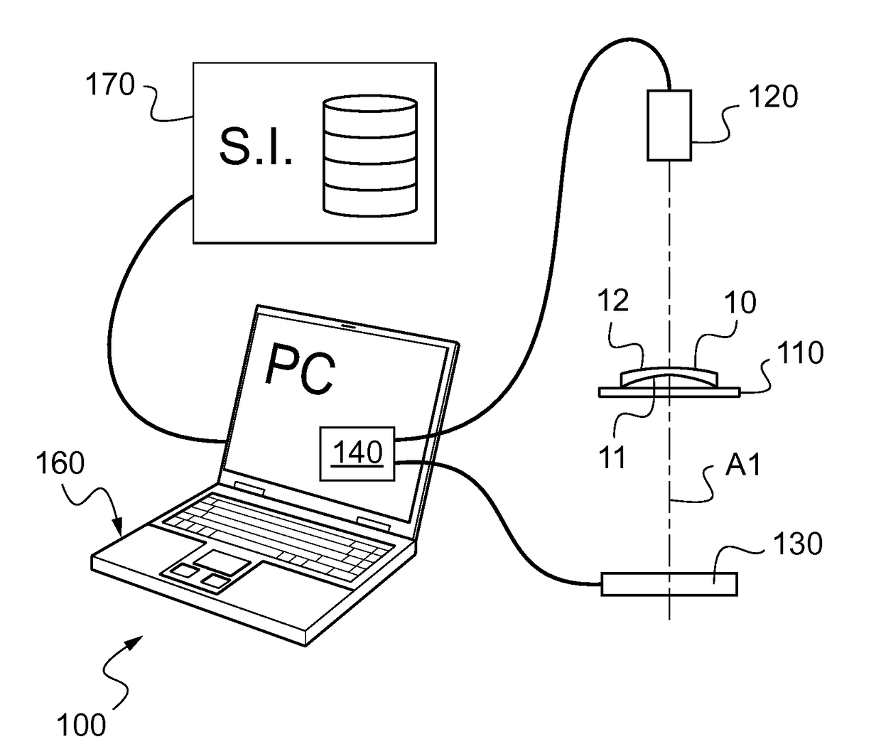
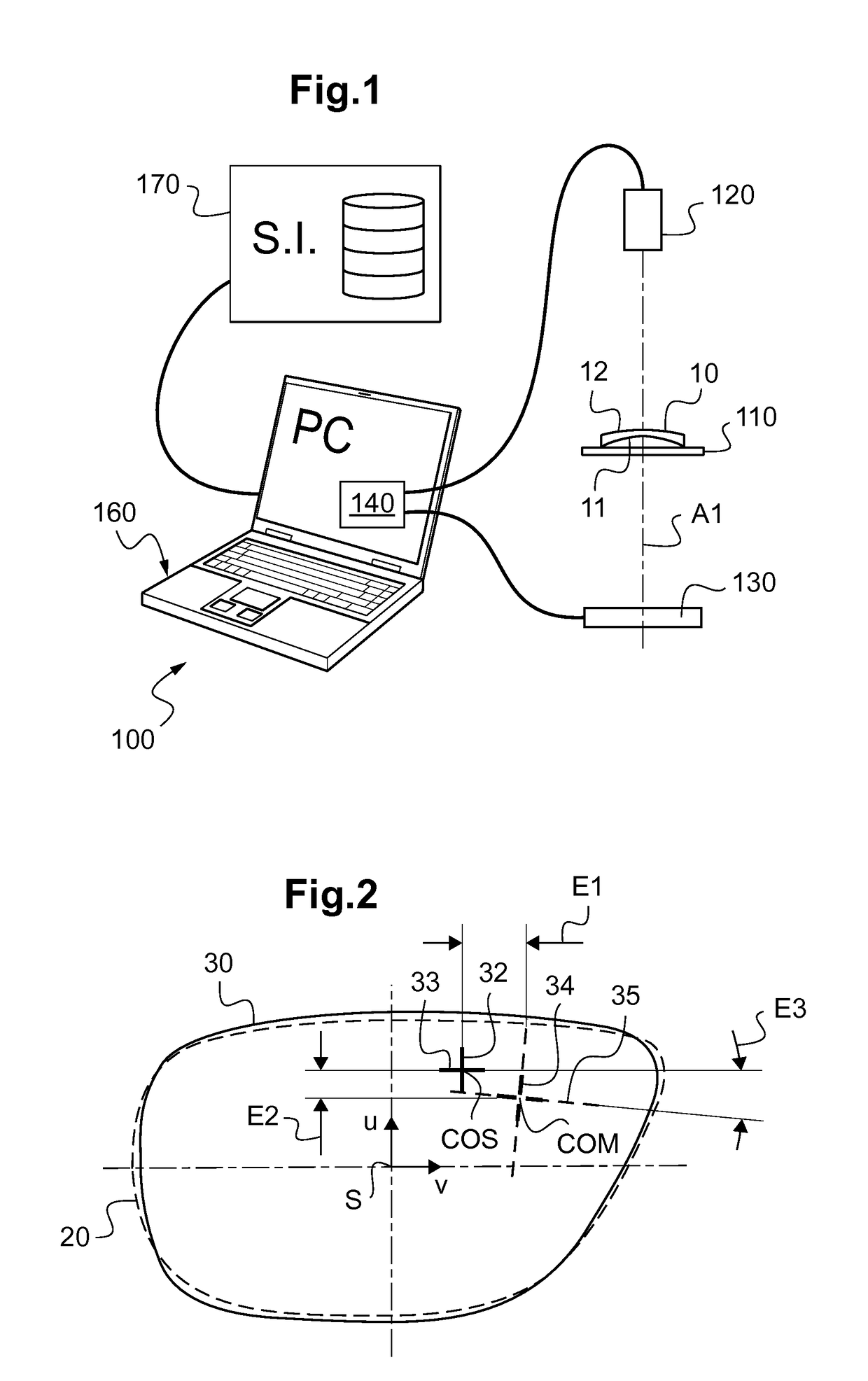
[0138]When the edged lens 10 is a unifocal lens, in step d), the operator or the computer 160 automatically triggers at least one second capture of an image of the edged lens 10, while displaying behind this edged lens 10, with respect to the image-capturing device, the stationary pattern, which for example is the Hartmann matrix.

[0139]Thus, in step d), the second image captured by virtue of said image-capturing device is the image of the stationary pattern consisting of the Hartmann matrix through the edged ophthalmic lens 10, and said optical characteristic is determined depending on this second image.

[0140]This Hartmann matrix is a matrix of dots the relative positions of which are known in the plane of display of the matrix.

[0141]This Hartmann matrix may here be displayed by the displaying device 130. It then constitutes one of the patterns that this device is suitable for displaying.

[0142]In practice here the Hartmann matrix is then displayed on the LCD screen of the displaying...

second embodiment

[0148]According to step d) in the case of a unifocal edged lens, in a step d1) prior to step a), the edged ophthalmic lens is placed in a lensmeter and a mark is made on said edged ophthalmic lens, said mark indicating the optical center and / or the optical axis on said ophthalmic lens, and in a step d2) the image of this mark is identified in said first image captured in step b).

[0149]In practice, the lensmeter allows 3 dots representing the optical center and the direction of the cylinder axis to be marked on the front face of the edged lens, these dots being easily identifiable by image processing.

[0150]The measured optical characteristics of the edged ophthalmic lens are here obtained directly in the coordinate system of the first image captured in step b).

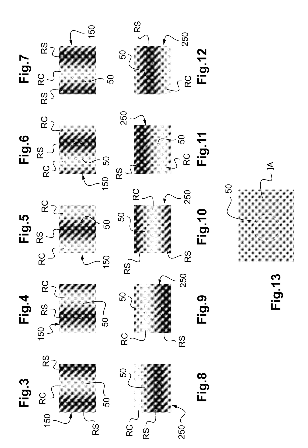
[0151]When the edged lens 10 is a progressive lens, in step d), by virtue of said image-capturing device 120, a plurality of images of the scrolling pattern 150, 250 displayed on said displaying device 130 are captured through ...


PUM


Abstract

Disclosed is a method for checking at least one geometric characteristic and one optical characteristic of a trimmed ophthalmic lens (10) including the following steps: a) arranging the trimmed ophthalmic lens on a support (110), b) capturing at least one image of the trimmed ophthalmic lens, c) determining, from the image, a measured geometric characteristic of the trimmed ophthalmic lens, d) determining at least one measured optical characteristic of the trimmed ophthalmic lens in a reference frame of the image captured in step b), e) comparing the measured geometric characteristic associated with the measured optical characteristic to a predefined desired ophthalmic lens model, including at least one desired geometric characteristic and one associated desired optical characteristic. Also disclosed is an associated checking device.

Description

TECHNICAL FIELD OF THE INVENTION[0001]Generally, the present invention relates to the field of methods for checking edged ophthalmic lenses.[0002]It more particularly relates to a method for checking a geometric characteristic and an optical characteristic of an edged ophthalmic lens.[0003]It also relates to a device for checking at least one geometric and / or optical characteristic of an edged ophthalmic lens.TECHNOLOGICAL BACKGROUND[0004]Ophthalmic lenses intended to be mounted in a particular spectacle frame are manufactured from an initial circular lens having the optical characteristics required by the prescription of the wearer.[0005]To this end, this initial lens is edged so as to have an outline suitable for the spectacle frame chosen by the wearer, this outline being centered in the initial lens depending on geometrico-morphological characteristics of the wearer, such as interpupillary distance and / or depending on characteristics related to the position of the frame on the f...

Claims


Application Information

Patent Timeline
IPC IPC(8): G01M11/02G01B11/24G01N21/958G02C13/00
CPCG01M11/0242G01B11/24G01N21/958G02C13/005G01M11/0221G01M11/025G01M11/0264G01N2021/9583
Inventor LEMAIRE, CEDRICLIPPENS, XAVIER
Owner ESSILOR INT CIE GEN DOPTIQUE
Learn More