Luminescent device

a technology of luminescent devices and perovskite crystals, which is applied in the direction of luminescent compositions, optical elements, instruments, etc., can solve the problems of decreasing the photoluminescence yield of perovskite crystals, and achieve the effect of improving the luminescent yield of luminescent devices

Active Publication Date: 2018-07-12
CAMBRIDGE ENTERPRISE LTD +1
View PDF3 Cites 13 Cited by
  • Summary
  • Abstract
  • Description
  • Claims
  • Application Information

AI Technical Summary

Benefits of technology

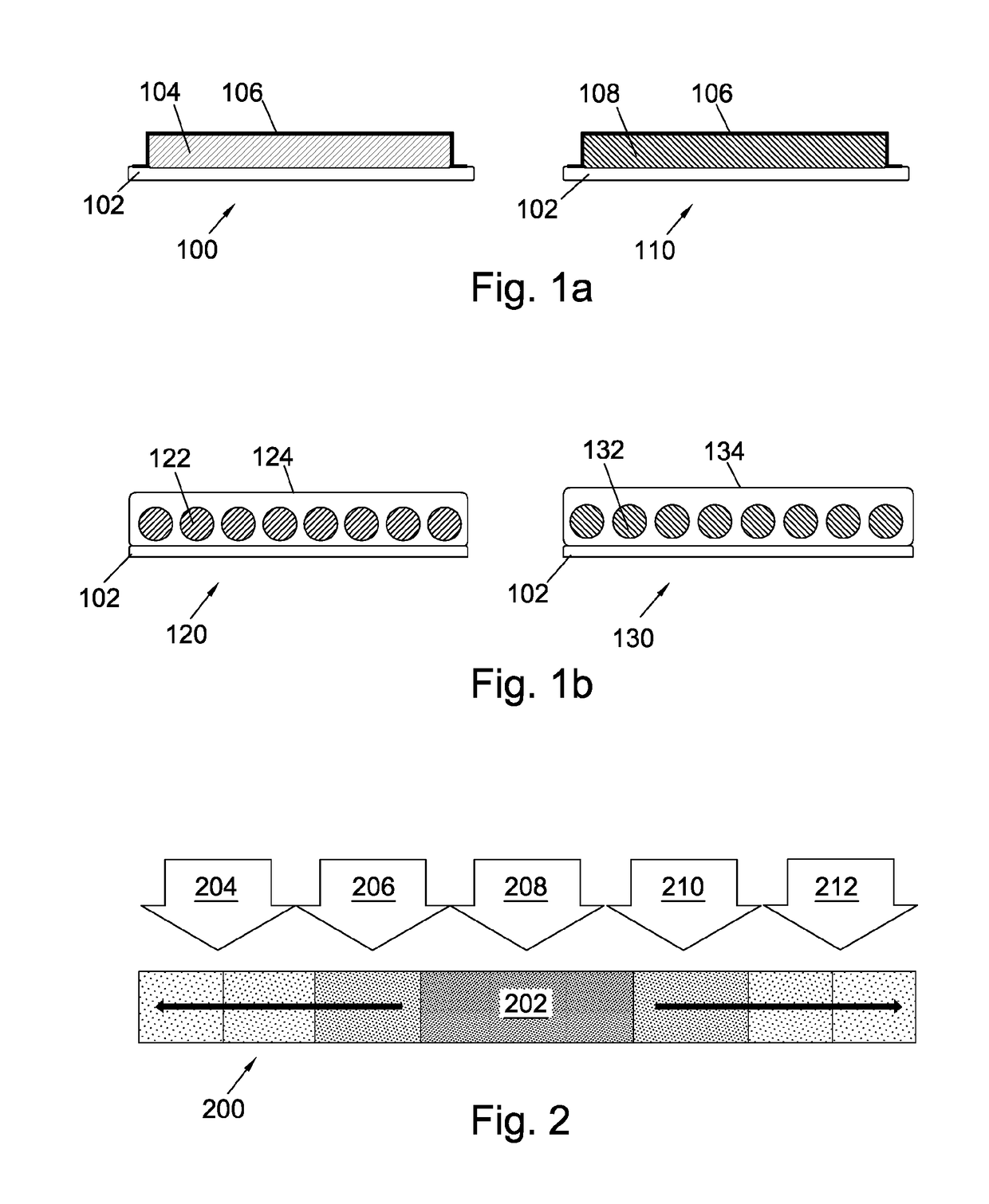
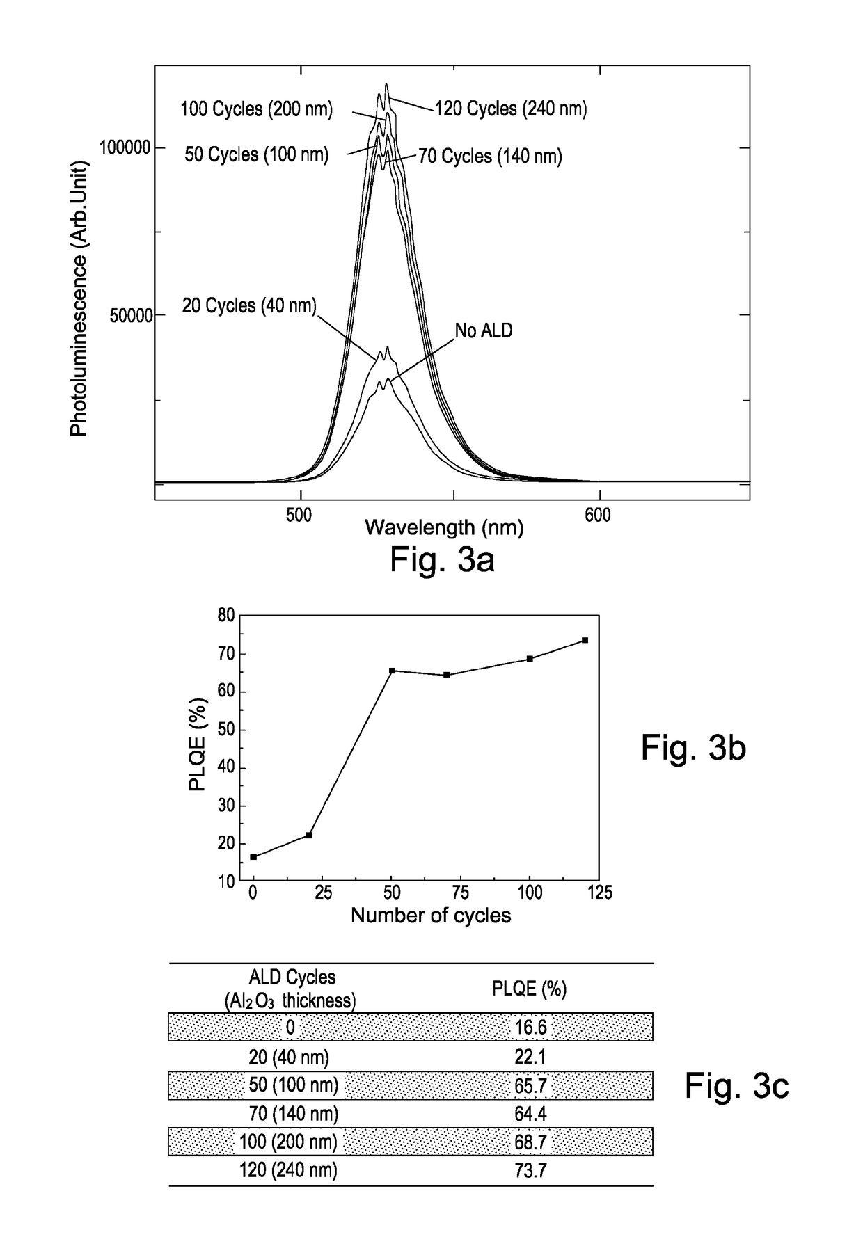
[0077]As will be further described below, the method may allow for enhancement of the luminescent yield of the luminescent device, and the luminescent yield may not decrease upon deposition of the layer or network comprising the metal oxide and metal hydroxide onto the perovskite crystals.
[0078]The vapour-based technique described herein may make the use of ligand exchange processes redundant. The method described herein therefore advantageously allows cross-linking the perovskite crystals without altering the original crystal arrangement, thereby allowing much of the original structural and electronics properties of the perovskite crystal film to be preserved.

Problems solved by technology

This is a surprising result as one would generally expect that an encapsulation layer or matrix deposited onto the film comprising perovskite crystals would result in an introduction of electronic defect states at or near the surface of the perovskite material during deposition of the encapsulation layer or matrix, thereby decreasing the photoluminescence yield of the perovskite crystals.

Method used


Image

  • Luminescent device
  • Luminescent device
  • Luminescent device

Examples


Embodiment Construction

[0102]In the following examples, the film comprising perovskite crystals consists solely of perovskite. We note that references throughout the specification to a film comprising perovskite crystals consisting solely of perovskite include, inter alia, pure perovskite crystal films as well as perovskite crystal films in which ligands bind to the perovskite crystals. These ligands may be used during synthesis of the perovskite crystals, in particular to avoid agglomeration of perovskite crystals during synthesis, as will be known to those skilled in the art. These ligands may be organic ligands. In the examples described herein, the ligands used for synthesising the perovskite crystals are oleylamine or oleic acid.

[0103]In some examples, the above-described vapour-based cross-linking method may be used to covalently bind the precursor material from which the insulating encapsulation layer, matrix or network is formed to the ligands which are used during synthesis of the perovskite crys...


PUM

PropertyMeasurementUnit
thickaaaaaaaaaa
thickaaaaaaaaaa
diameteraaaaaaaaaa

Abstract

We describe a luminescent device (120, 130) comprising a substrate (102) and a film comprising perovskite crystals (122, 132) deposited on the substrate, wherein the film comprising perovskite crystals is encapsulated with a layer (124, 134)) or within a matrix (124, 134) of an insulating oxide or an insulating nitride.

Description

FIELD OF THE INVENTION[0001]This invention generally relates to luminescent devices comprising a film comprising perovskite crystals encapsulated with a layer or within a matrix of an insulating oxide, an insulating nitride or an insulating metal oxide / hydroxide network, and methods for preparing such luminescent devices.BACKGROUND TO THE INVENTION[0002]We have previously described, in our co-pending applications GB 1407606.1 and GB 1421133.8, perovskite-based light-emitting devices. Light-emitting devices based on earth-abundant organometal halide perovskite materials have recently been shown to exhibit bright and colour-controlled electroluminescence (see Tan, Z.-K. et al., Nature Nanotechnology 9, 687-692 (2014)). Typical examples of devices disclosed in Tan et al. include TiO2 / CH3NH3PbI3−xClx / F8 film structures. In some of these devices, a thin layer of Al2O3 is included above the TiO2 and under the CH3NH3PbI3−xClx as a layer between the two to optimise device efficiencies and m...

Claims


Application Information

Patent Timeline
Patent Type & Authority Applications(United States)
IPC IPC(8): G02B1/02H01L51/00H01L51/50G02B1/04
CPCG02B1/02H01L51/005H01L51/502G02B1/04H01L51/0013B82Y20/00B82Y40/00H10K59/38H10K85/60H10K85/631H10K50/115H10K50/85H10K50/84H10K2102/00H10K71/00G02B5/206H10K2102/103C09K11/06H01L21/0228C09K2211/1014H10K71/18
Inventor FRIEND, RICHARD HENRYLI, GUANGRUDI, DAWEIMOGHADDAM, REZA SABERITAN, ZHI KUANG
Owner CAMBRIDGE ENTERPRISE LTD
Why Eureka
Try Eureka