Pulse oximetry sensors and methods

a pulse oximeter and pulse oximeter technology, applied in the field of biological probes, sensors, methods, etc., can solve the problem of insufficient pulse amplitude for a pulse oximeter to reliably measure blood or blood circulation characteristics

Inactive Publication Date: 2018-07-19
GENERAL ELECTRIC CO
View PDF9 Cites 3 Cited by
  • Summary
  • Abstract
  • Description
  • Claims
  • Application Information

AI Technical Summary

Benefits of technology

[0005]Thus, blood from the internal carotid artery, which does not undergo substantial ANS regulation, may be monito

Problems solved by technology

Vasoconstriction, which may be regulated by the autonomic nervous system (ANS), may result in insuffici

Method used


Image

  • Pulse oximetry sensors and methods
  • Pulse oximetry sensors and methods
  • Pulse oximetry sensors and methods

Examples


first embodiment

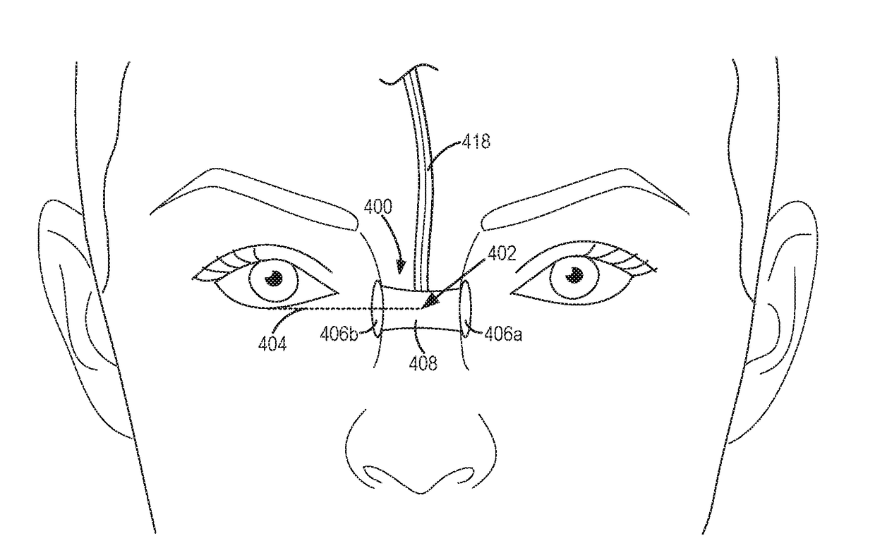
[0043]Turning now to FIG. 4, a partial front view of a face of a subject wearing a nasal pulse oximetry probe 400 is shown. The center of the root of the nasal bridge is indicated at 402. The exact location of the center of the root of the nasal bridge 402 may vary for each patient. In the example of FIG. 4, the center of the root of the nasal bridge 402 is level with the bottom of the eye, as indicated by dashed line 404. However, in other examples, the center of the root of the nasal bridge 402 may be higher than dashed line 404 (e.g., more toward the eyebrows) or lower than dashed line 404 (e.g., more toward the lips). For example, the center of the root of the nasal bridge may lie along a central axis of the eyes (e.g., an axis that passes through the caruncula lacrimalis of each eye).

[0044]Bridge portion 408 of the nasal pulse oximetry probe (e.g., probe 200 of FIG. 2A) is shaped to be centered on the center of the root of the nasal bridge 402. In one example, the probe may inc...

second embodiment

[0046]Turning now to FIG. 5, a partial front view of a face of a subject wearing a nasal pulse oximetry probe 500 is shown. Like components of FIGS. 4 and 5 are numbered similarly (e.g., 408 corresponds to 508). Whereas the nasal pulse oximetry probe of FIG. 4 may be attached to the patient with adhesive, the probe of FIG. 5 additionally or alternatively includes an attachment mechanism in the form of an eyeglass-type frame 510, which rests on ears 516 of the patient. The size and shape of frame 510 may vary. For example, frame 510 may be manufactured at different sizes and configurations to accommodate different types of patients (e.g., neonates, infants, pediatrics, and adults). In particular, the width of frame 510 may vary to accommodate patients with different head widths. The mechanisms for adjusting the probe widths may be part of the frame, which makes one frame suitable for broad range of head widths. Regardless of the size or shape of the frame 510, the frame 510 is config...


PUM


Abstract

Methods and systems are provided for a nasal pulse oximetry probe configured to measure blood originating from the internal carotid artery. One example system includes a light emitter and a light detector coupled to a substrate and an attachment mechanism configured to couple the nasal pulse oximetry probe to a nose of a patient, the light emitter and light detector positioned on opposite sides of the nose at the root of the nasal bridge.

Description

FIELD[0001]Embodiments of the subject matter disclosed herein relate to biological probes, sensors, and methods, and in particular, to photoplethysmography probes, sensors, and methods.BACKGROUND[0002]Photoplethysmography (PPG) relates to the use of optical signals transmitted through or reflected by blood-perfused tissues for monitoring a physiological parameter of a subject (also referred to as a patient herein). In this technique, one or more emitters are used to direct light at a tissue, and one or more detectors are used to detect the light that is transmitted through or reflected by the tissue. The volume of blood of the tissue affects the amount of light that is transmitted or reflected, which is output as a PPG signal. As the blood volume in a tissue changes with each heartbeat, the PPG signal also varies with each heartbeat.[0003]Pulse oximetry is, at present, the standard of care for continuously monitoring arterial oxygen saturation (SpO2). Pulse oximeters include PPG pro...

Claims


Application Information

Patent Timeline
IPC IPC(8): A61B5/1455A61B5/08A61B5/00A61B5/021A61B5/026
CPCA61B5/14551A61B5/0816A61B5/0261A61B5/02125A61B5/7278A61B5/6819
Inventor HUIKU, MATTI VELI TAPANIRUPONEN, PELLERVOLAMMINMAKI, SAKARI MATIAS
Owner GENERAL ELECTRIC CO
Why Eureka
Try Eureka