Heating oximeter
a technology of oximeter and oximeter body, which is applied in the field of heating oximeter, can solve the problems of complex configuration of sensor unit, difficulty in continuous measurement during activity, and risk of increasing cost, and achieve the effect of improving the measurement accuracy of oxygen saturation, resistance value, and accurate measuremen
- Summary
- Abstract
- Description
- Claims
- Application Information
AI Technical Summary
Benefits of technology
Problems solved by technology
Method used
Image
Examples
first preferred embodiment
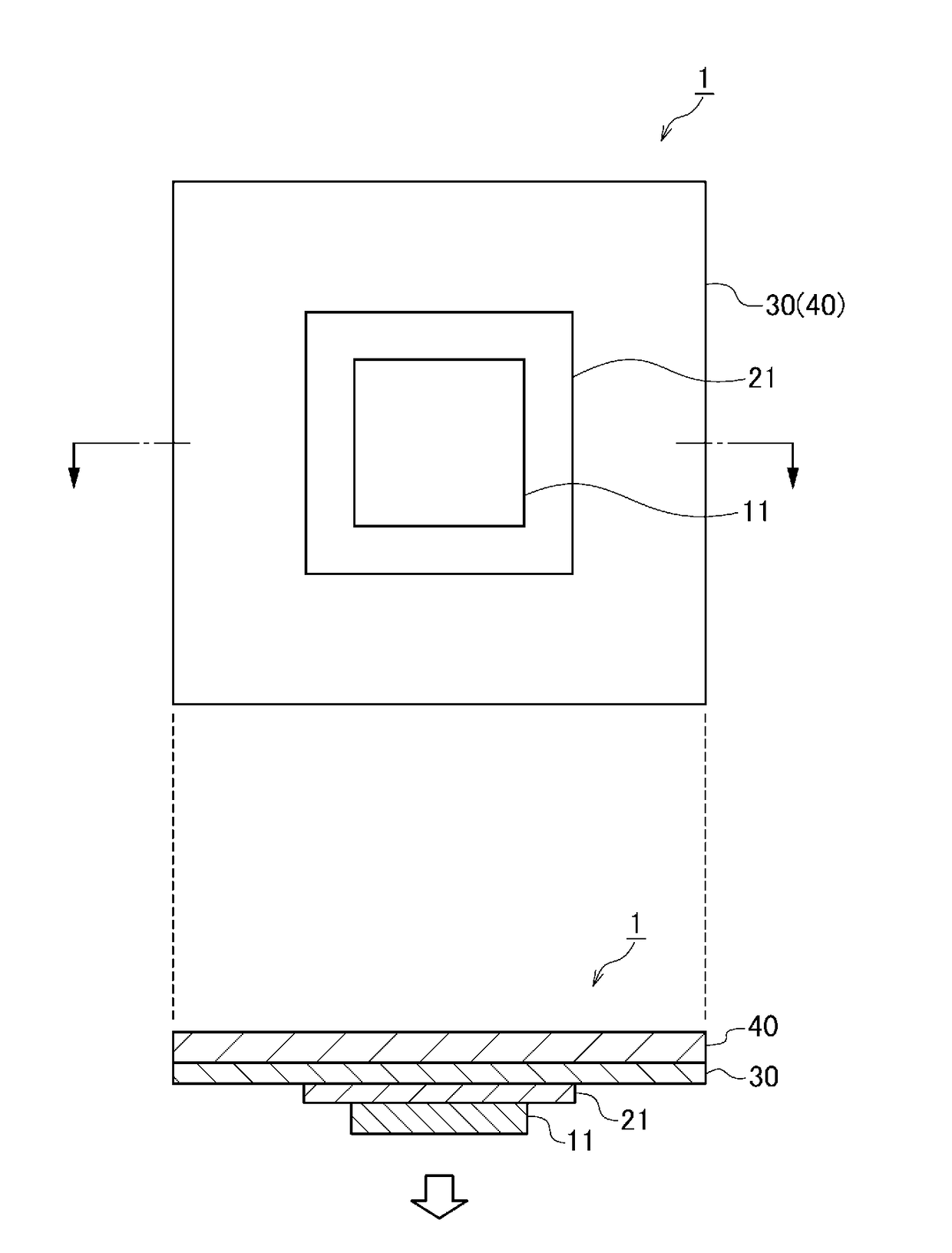
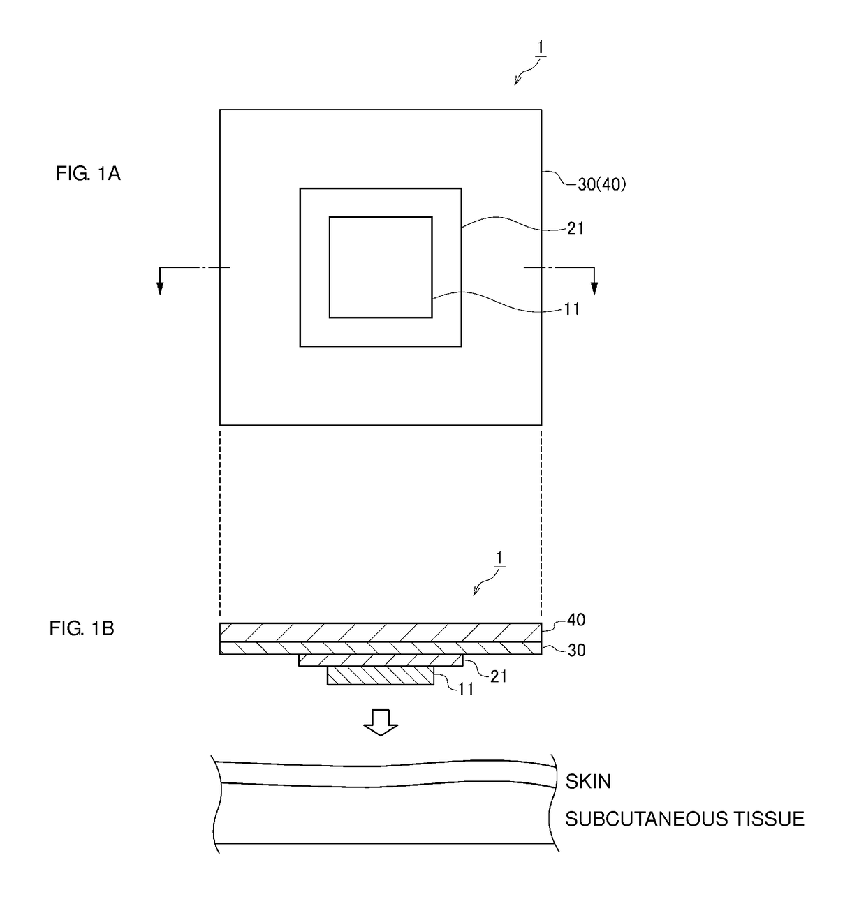
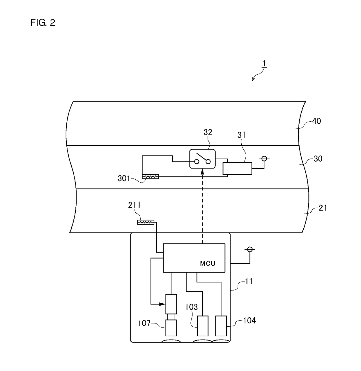
[0032]First, the configuration of a heating pulse oximeter (hereinafter, simply referred to as a “heating oximeter”) 1 according to a first preferred embodiment will be described with reference to FIG. 1 to FIG. 3. FIG. 1A is a plan view and FIG. 1B is a longitudinal cross-sectional view of the heating oximeter 1. FIG. 2 is a view illustrating a main component of the heating oximeter 1 in an enlarged manner. FIG. 3 is a block diagram illustrating the configuration of an oxygen saturation acquisition assembly 11 of the heating oximeter 1.
[0033]The heating oximeter 1 has a heating function of heating a measurement site, increasing a blood flow volume in the measurement site to cause arterialization, and optically measuring oxygen saturation (e.g., a presence ratio between oxygenated hemoglobin and reduced hemoglobin) using light absorption characteristics of hemoglobin (i.e., oxygenated hemoglobin and reduced hemoglobin) in blood, specific details of this will be described later. In p...
second preferred embodiment
[0063]Next, a heating oximeter 2 according to a second preferred embodiment will be described with reference to FIGS. 5 and 6. Description of the same or similar configurations as or to those in the above-described first preferred embodiment is simplified or omitted and different points are mainly described. FIG. 5 is a longitudinal cross-sectional view of the heating oximeter 2. FIG. 6 is a view illustrating a main component of the heating oximeter 2 in an enlarged manner. It should be noted that the same reference numerals denote the same or equivalent components as or to those in the first preferred embodiment in FIGS. 5 and 6.
[0064]The heating oximeter 2 is different from the heating oximeter 1 according to the above-described first preferred embodiment in a point that it further includes a third temperature detector 23 and in a point that it includes an oxygen saturation acquisition assembly 12 instead of the oxygen saturation acquisition assembly 11. It should be noted that ot...
third preferred embodiment
[0073]Next, a heating oximeter 3 according to a third preferred embodiment of the present invention will be described with reference to FIG. 7. Description of the same or similar configurations as or to those in the above-described first preferred embodiment is simplified or omitted and different points are mainly described. FIG. 7 is a longitudinal cross-sectional view of the heating oximeter 3. It should be noted that the same reference numerals denote the same or equivalent components as or to those in the first preferred embodiment in FIG. 7.
[0074]The heating oximeter 3 is different from the heating oximeter 1 according to the above-described first preferred embodiment in a point that it includes a heat generation portion 33 instead of the heat generation portion 30. It should be noted that other configurations are the same as or similar to those of the above-described heating oximeter 1 and detail description thereof is therefore omitted herein.
[0075]A resistance value of the h...
PUM
 Abstract
Description
Claims
Application Information
 - R&D
- Intellectual Property
- Life Sciences
- Materials
- Tech Scout
- Unparalleled Data Quality
- Higher Quality Content
- 60% Fewer Hallucinations
Browse by: Latest US Patents, China's latest patents, Technical Efficacy Thesaurus, Application Domain, Technology Topic, Popular Technical Reports.
© 2025 PatSnap. All rights reserved.Legal|Privacy policy|Modern Slavery Act Transparency Statement|Sitemap|About US| Contact US: help@patsnap.com


