Apparatus for maintaining a controlled environment

a technology of controlled environment and apparatus, which is applied in the direction of drying chamber/container, drying machine, light and heating apparatus, etc., can solve the problems of affecting the stability of substances, affecting the lyophilization of substances, and preventing the rehydration of substances, etc., to achieve low moisture content, low moisture content, and high nitrogen environment

Active Publication Date: 2018-07-26
GEN PROBE INC
View PDF0 Cites 12 Cited by
  • Summary
  • Abstract
  • Description
  • Claims
  • Application Information

AI Technical Summary

Benefits of technology

[0011]In various embodiments, the base interior is configured to support one or more receptacles therein. In various embodiments, the receptacles may each comprise a plurality of lyophilization wells configured to be sealed and a plastic and/or low moisture vapor transmission rate material, such as a cyclic olefin copolymer. Moreover, in various embodiments, the top surface of the bottom plate comprises one or more receptacle receiving portions formed thereon, each of the receptacle receiving portions having features that conform to at least a bottom end of the one or more receptacles to be received thereon and are constructed to conduct heat between the base and the one or more receptacles supported thereon. In various embodiments, each of the one or more receptacles to be supported within the lyophilization nest comprise a plurality of lyophilization wells, and each of the receptacle receiving portions comprises a plurality of well receiving features conforming to the shapes of at least the bottom ends of lyophilization wells of the corresponding receptacle. Moreover, in various embodiments, the lyophilization nest additionally comprises one or more receptacle frames situated on a top surface of the bottom plate, each receptacle frame configured to support a plurality of receptacles (e.g., four receptacles).
[0012]In various embodiments the lyophilization nest further comprises one or more fasteners for securing the cover to the base. The fasteners of the lyophilization nest are configured to compress the gasket between the base edge and the cover edge to form the air tight seal when the base and the cover are in the closed relationship. As an example, the fastener further comprises a base engagement member such as a base pin, a cover engagement member such as a cam lever, and a linking member that links the other two members. As further examples, the fastener can be a latch, a bolt, a clamp, or other structure that compresses the gasket between the base edge and the cover edge to form the air tight seal when the base and the cover are in the closed relationship.
[0013]Various embodiments herein are directed to a lyophilization system for lyophilizing one or more substances, the lyophilization system comprising: a sealable enclosure defining a chamber and having a plurality of shelves. In various embodiments, the plurality of shelves are a top shelf and a bottom shelf contained within the chamber. In various embodiments, the plurality of shelves are at least one top shelf and at least one bottom shelf. In various embodiments, the plurality of shelves are a top shelf, a bottom shelf and at least one middle shelf that can be referred to as a top shelf and/or bottom shelf depending on its spatial relationship to a lyophilization nest in the lyophilization system. In various embodiments, the plurality of shelves are a top shelf, a bottom shelf and at least two middle shelves that can be referred to as a top shelf and/or bottom shelf depending on their spatial relationship to a lyophilization nest in the lyophilization system. In various embodiments, the plurality of shelves are at least one top shelf and at least one bottom shelf, each relative to a lyophilization nest in the lyophilization system. In various embodiments, a lyophilization nest is situated on a bottom shelf. In various embodiments, at least one of a top shelf and a bottom shelf is capable of an automated movement that causes the top shelf to engage the sealing elements, thereby altering the sealing elements and the corresponding vent holes from the open configuration to the closed configuration. In various embodiments, the top shelf is positioned above the lyophilization nest and is configured for automated downward movement toward a top surface of the cover of the lyophilization nest.
[0014]Various embodiments herein are directed to a lyophilization system for lyophilizing one or more substances, the lyophilization system comprising: a sealable enclosure defining a chamber and having at least one top shelf and at least one bottom shelf contained within the chamber; and at least one lyophilization nest situated on a bottom shelf. In various

Problems solved by technology

After lyophilization is complete, the seal on the lyophilizer is released, and consequently the controlled environment within the lyophilizer is diluted with the air surrounding the lyophilizer, which can be detrimental to lyophilized substances.
Introducing moisture to the lyophilized substances can negatively affect the stability of the substances.
Thus, the seal impedes rehydration of substances that results from absorbing water vapor from the atmosphere.
The process of sealing receptacles after removal from the lyophilizer exposes the individual substances to unfavorable environmental conditions during the period of time between removal of the receptacle from the lyophilizer until the receptacle is sealed.
As a result, the lyophilized substances in each vial or well of the multi-well plate may be exposed to uncontrolled and potentially unfavorable environmental conditions, including moisture, prior to being sealed.
However, manipulation of the receptacles may be cumbersome when using a glove box.
Additionally, the moisture vapor exposure time during transfer of the receptacles from the lyophilizer to the glovebox may still b

Method used


Image

  • Apparatus for maintaining a controlled environment
  • Apparatus for maintaining a controlled environment
  • Apparatus for maintaining a controlled environment

Examples


Embodiment Construction

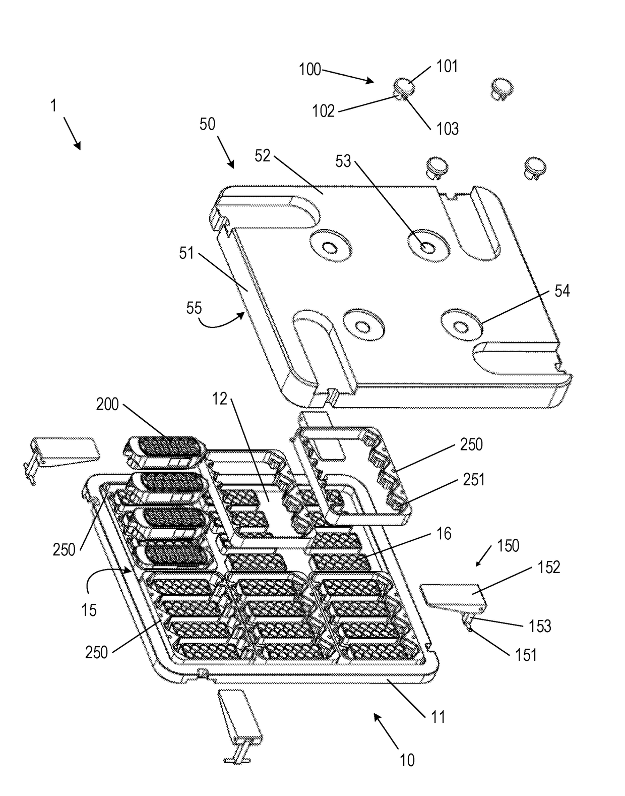
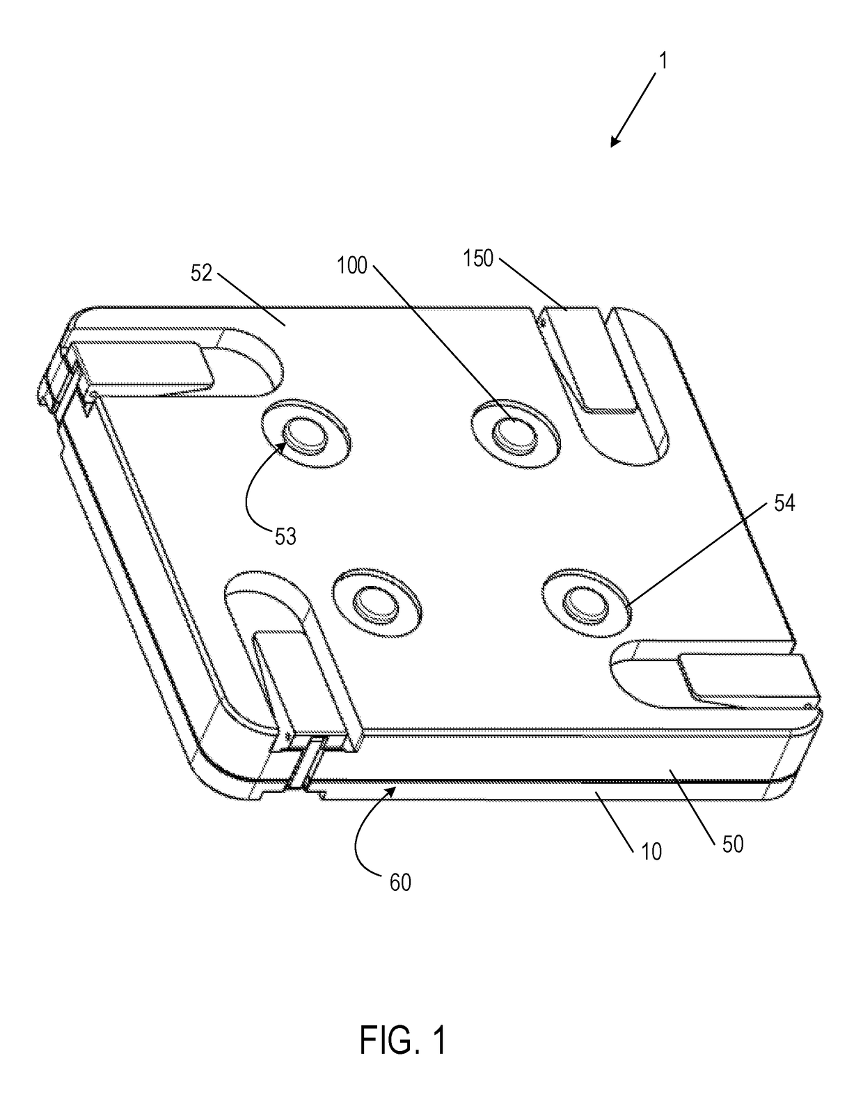
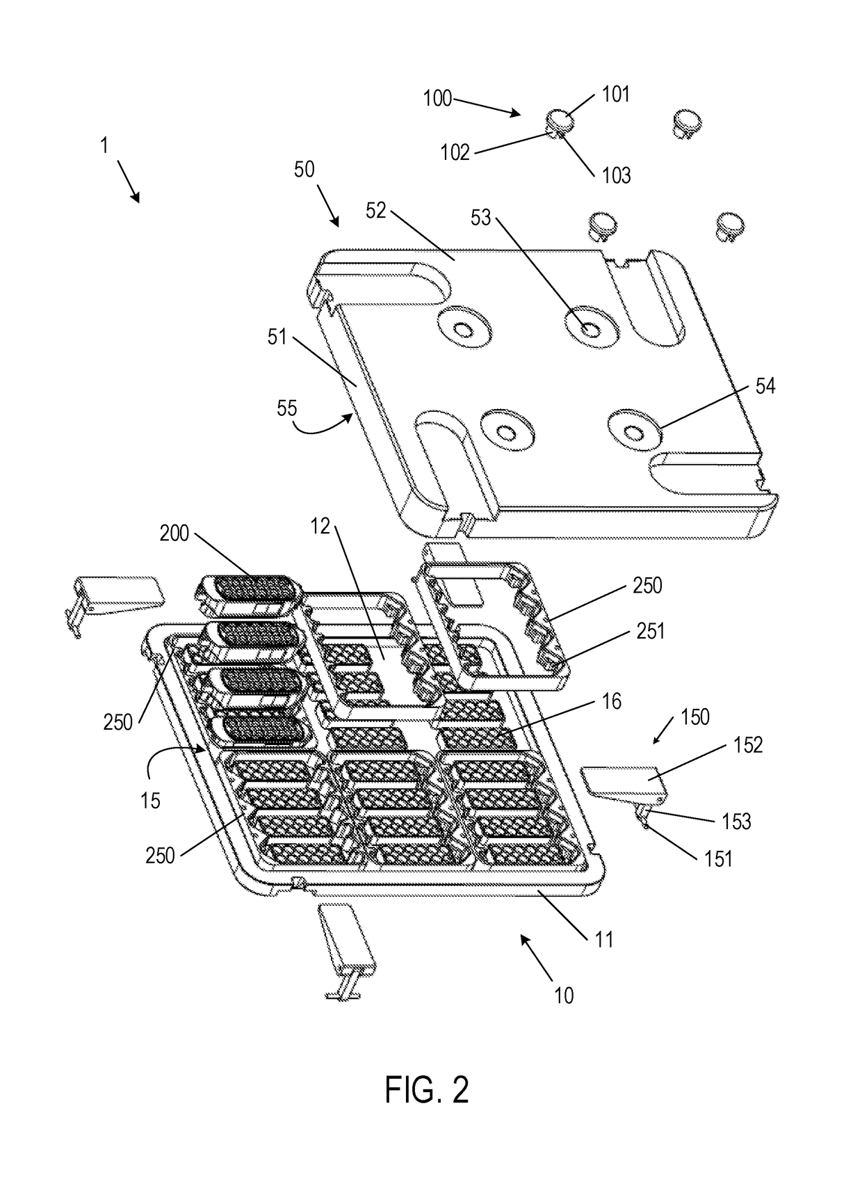
[0026]The lyophilization nest will now be described more fully hereinafter with reference to the accompanying drawings, in which some, but not all embodiments of the nest are shown. Indeed, the lyophilization nest may be embodied in many different forms and should not be construed as limited to the embodiments set forth herein. Rather, these embodiments are provided so that this disclosure will satisfy applicable legal requirements. Like numbers refer to like elements throughout.

[0027]Lyophilization is a well-known process for drying a substance so to preserve that substance. The primary mechanism that allows for lyophilization is sublimation, whereby ice is directly converted to water vapor, without passing through the intermediary stage of a liquid. Rather than through heating, this is done by removal of pressure so that the ice boils without melting. The result is a substance whose structure is largely preserved, which has a negligible water content, and which can be stored at ro...


PUM


Abstract

A lyophilization nest and method of using the same is described herein. In various embodiments, the lyophilization nest is configured to support one or more receptacles each supporting one or more substances within an interior space of the lyophilization nest. The interior space may be in fluid communication with the exterior of the lyophilization nest through one or more vent holes extending through a surface of the lyophilization nest. Each of the one or more vent holes have a corresponding sealing element configured to selectively form an air-tight seal within the vent holes, such that a controlled environment may be maintained within the interior space when the ambient conditions surrounding the lyophilization nest are not lyophilization conditions. The one or more sealing elements may be operable while the lyophilization nest is positioned within a sealed lyophilizer by depressing the sealing elements into corresponding vent holes to form the air-tight seal.

Description

CROSS REFERENCE TO RELATED APPLICATIONS[0001]This application claims the benefit of priority of U.S. provisional application No. 62 / 200,370, which was filed on Aug. 3, 2015, and which is incorporated herein by reference.BACKGROUND[0002]Lyophilization is a process used to remove water from substances allowing these substances to be stored for longer periods of time without material deterioration. Typically these substances are of biological or synthetic origin and may include antibiotics, pharmaceuticals, chemicals, sera, vaccines, cells, tissues, protein and / or nucleic acids.[0003]Substances can be lyophilized by placing individual vials or a multi-well plate containing one or more substances into a lyophilizer, which generates and maintains a controlled environment therein during the lyophilization process. The environmental factors that are controlled by the lyophilizer include, but are not limited to, temperature, air pressure / vacuum level, humidity, and / or gas content. After lyo...

Claims


Application Information

Patent Timeline
IPC IPC(8): F26B5/06F26B25/06B01L1/02
CPCF26B5/06F26B25/063B01L1/02B01L2300/1894B01L2200/0689B01L2300/0829B01L2300/042B01L2400/049A01N1/0289B01L9/06B01L7/00A01N1/0252A01N1/0284
Inventor KNIGHT, BYRON J.
Owner GEN PROBE INC
Why Eureka
Try Eureka