Detector for optically detecting at least one object

a detector and optical detection technology, applied in the field of detectors, can solve the problems of inherently limited use of fip measurement principles by large-area sensors in many cases

Active Publication Date: 2018-07-26
TRINAMIX GMBH
View PDF7 Cites 34 Cited by
  • Summary
  • Abstract
  • Description
  • Claims
  • Application Information

AI Technical Summary

Benefits of technology

[0140]The transfer device can for example comprise one or a plurality of mirrors and/or beam splitters and/or beam deflecting elements in order to influence a direction of the electromagnetic radiation. Alternatively or additionally, the transfer device can comprise one or a plurality of imaging elements which can have the effect of a converging lens and/or a diverging lens. By way of example, the optional transfer device can have one or a plurality of lenses and/or one or a plurality of convex and/or concave mirrors. Once again alternatively or additionally, the transfer device can have at least o

Problems solved by technology

Despite the advantages implied by the above-mentioned devices and detectors, several technical challenges remain.
Still, large area sensors in many cases are inherently limited in the use of the FiP measurement principle, specifically in case more than one light spot is to be investigated simultaneously.
Even thou

Method used


Image

  • Detector for optically detecting at least one object
  • Detector for optically detecting at least one object
  • Detector for optically detecting at least one object

Examples


Embodiment Construction

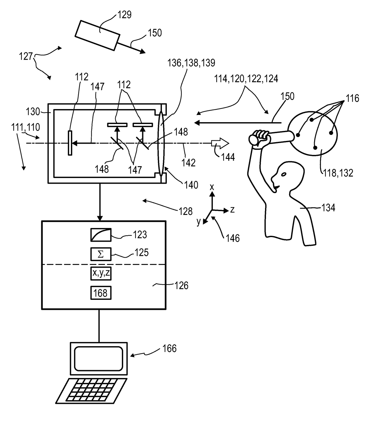
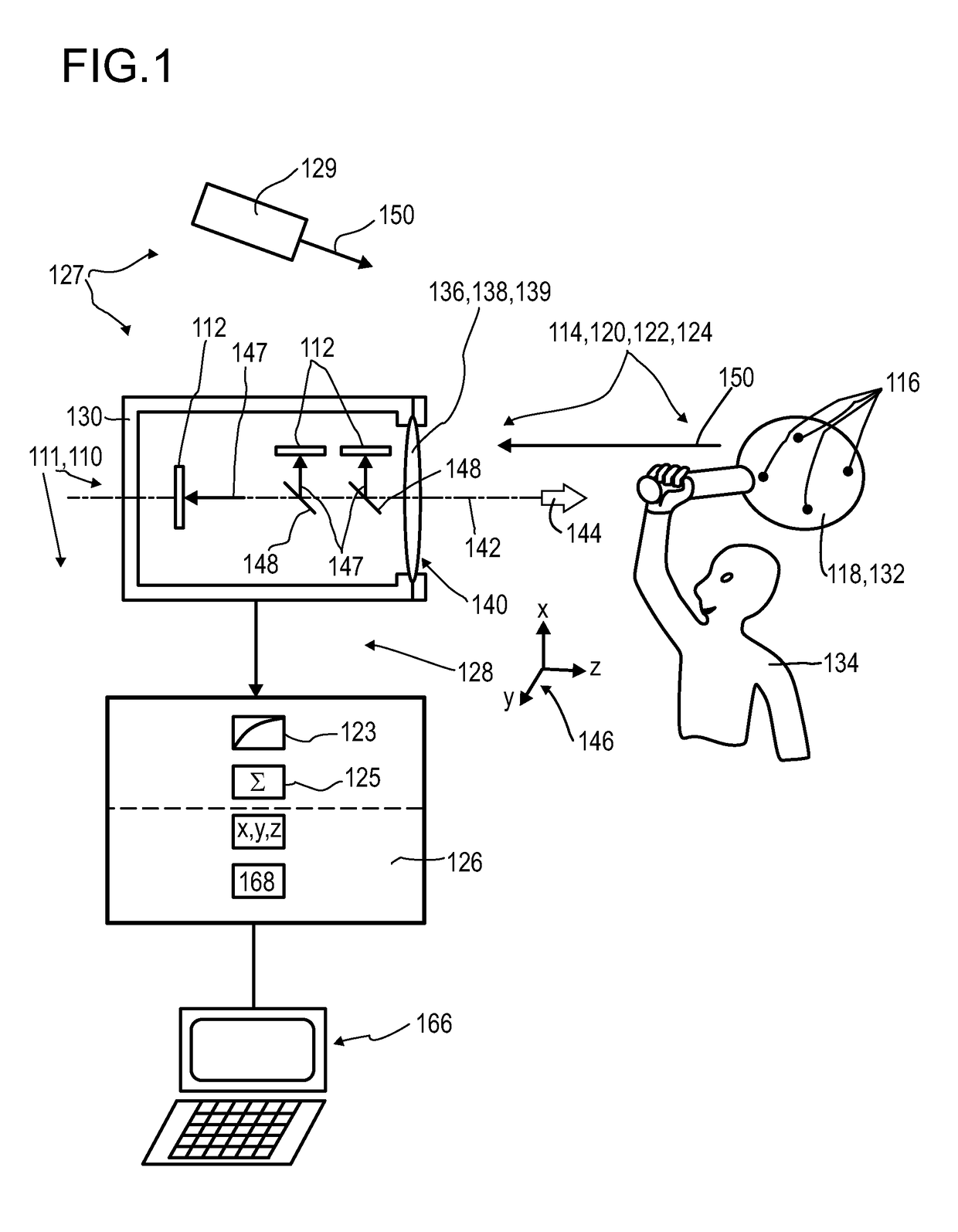
[0337]FIG. 1 shows, in a highly schematic illustration, an exemplary embodiment of a detector 110, having a plurality of optical sensors 112. The detector 110 specifically may be embodied as a camera 111 or may be part of a camera 111. The camera 111 may be made for imaging, specifically for 3D imaging, and may be made for acquiring standstill images and / or image sequences such as digital video clips. Other embodiments are feasible. FIG. 1 further shows an embodiment of a detector system 114, which, besides the at least one detector 110, comprises one or more beacon devices 116, which, in this exemplary embodiment, are attached and / or integrated into an object 118, the position of which shall be detected by using the detector 110. FIG. 1 further shows an exemplary embodiment of a human-machine interface 120, which comprises the at least one detector system 114, and, further, an entertainment device 122, which comprises the human-machine interface 120. The figure further shows an emb...


PUM


Abstract

A detector (110) for determining a position of at least one object (118) is proposed. The detector (110) comprises: —at least one optical sensor (112), the optical sensor (112) being configured to detect at least one light spot (156) generated by at least one light beam (150) propagating from the object (118) towards the detector (110), the optical sensor (112) having at least one matrix (152) of pixels (154), each pixel (154) being adapted to generate at least one pixel signal si,j in response to an illumination of the pixel (154) by the light beam (150); —at least one non-linearization device (123) configured to transform the pixel signals si,j of all pixels (154) i, j or of at least one group of pixels (154) into nonlinear pixel signals s′i,j, the nonlinear pixel signals s′i,j each being a nonlinear function of the power of the illumination pi,j of the respective pixel (154); —at least one summing device (125) configured to add up the nonlinearpixel signals s′i,j of all pixels (154) i, j or of the at least one group of pixels (154) and to generate at least one nonlinearsum signal S′=Σijs′ij; and —at least one evaluation device (126), the evaluation device (126) being configured to determine at least one longitudinal coordinate z of the object (118) by evaluating the nonlinear sum signal S′.

Description

FIELD OF THE INVENTION[0001]The invention relates to a detector, a detector system and a method for determining a position of at least one object. The invention further relates to a human-machine interface for exchanging at least one item of information between a user and a machine, an entertainment device, a tracking system, a camera, a scanning system and various uses of the detector device. The devices, systems, methods and uses according to the present invention specifically may be employed for example in various areas of daily life, gaming, traffic technology, production technology, security technology, photography such as digital photography or video photography for arts, documentation or technical purposes, medical technology or in the sciences. However, other applications are also possible.PRIOR ART[0002]A large number of optical sensors and photovoltaic devices are known from the prior art. While photovoltaic devices are generally used to convert electromagnetic radiation, ...

Claims


Application Information

Patent Timeline
IPC IPC(8): G01S5/16G01S3/784G01S17/66G01C3/08
CPCG01S5/16G01S3/784G01S17/66G01C3/08G01C3/32G01S7/4816G01S11/12G01S17/46G06F3/0325G06T2207/30204
Inventor SEND, ROBERTBRUDER, INGMARVALOUCH, SEBASTIAN
Owner TRINAMIX GMBH
Why Eureka
Try Eureka