Vibratory flowmeter test tones without ramp time

Active Publication Date: 2018-08-02
MICRO MOTION INC
View PDF1 Cites 1 Cited by
  • Summary
  • Abstract
  • Description
  • Claims
  • Application Information

AI Technical Summary

Benefits of technology

[0020]Preferably, the meter electronics is configured to recalculate a filt

Problems solved by technology

It is a problem that the one or more conduits may change character over time, wherein an init

Method used


Image

  • Vibratory flowmeter test tones without ramp time
  • Vibratory flowmeter test tones without ramp time
  • Vibratory flowmeter test tones without ramp time

Examples


Embodiment Construction

[0029]FIGS. 1-6 and the following description depict specific examples to teach those skilled in the art how to make and use the best mode of the invention. For the purpose of teaching inventive principles, some conventional aspects have been simplified or omitted. Those skilled in the art will appreciate variations from these examples that fall within the scope of the invention. Those skilled in the art will appreciate that the features described below can be combined in various ways to form multiple variations of the invention. As a result, the invention is not limited to the specific examples described below, but only by the claims and their equivalents.

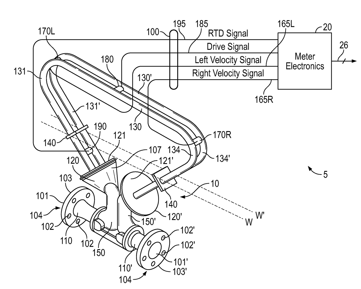
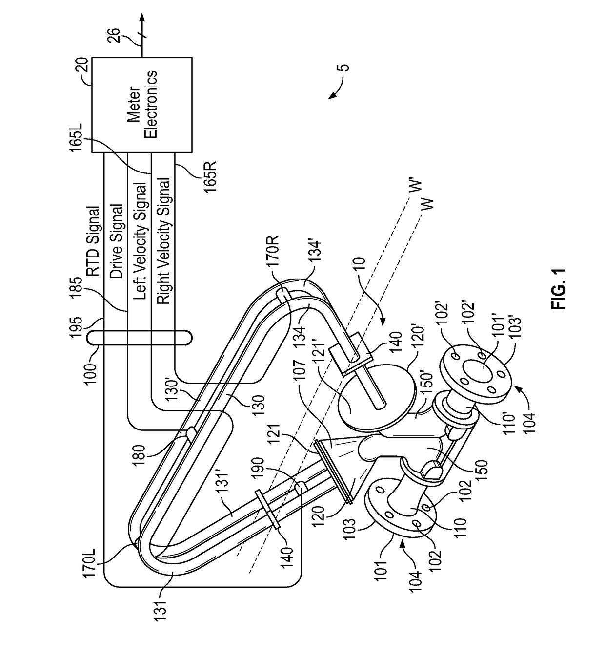
[0030]FIG. 1 shows a vibratory flowmeter 5 for improved meter verification according to an embodiment. The flowmeter 5 comprises a sensor assembly 10 and meter electronics 20 coupled to the sensor assembly 10. The sensor assembly 10 responds to at least a mass flow rate and / or a density of a process material. The meter electronics...


PUM


Abstract

A meter verification method for a vibratory flowmeter (5) is provided, comprising vibrating a sensor assembly (10) of the vibratory flowmeter (5) with a plurality of test tones in a vibration mode using a driver (180), wherein the plurality of test tones is applied substantially instantly, in the absence of a ramp function. A driver (180) current is determined, and response voltage of pickoff sensors (170L, 170R) are determined for the vibration mode. The instantaneous frequency of the pickoff sensor (170L, 170R) signals is measured, and a filter is applied to isolate the response at each of the plurality of test tones. The filter is also applied to the instantaneous frequency measurements. The same delay is applied to the frequency measurements and the response at each of the test tones. A meter stiffness value (216) is generated using the current (230) and the response voltage (231), and proper operation of the vibratory flowmeter (5) is verified using the meter stiffness value (216).

Description

TECHNICAL FIELD[0001]The present invention relates to a vibratory flowmeter and method, and more particularly, to an improved vibratory flowmeter and method for meter verification.BACKGROUND OF THE INVENTION[0002]Vibrating conduit sensors, such as Coriolis mass flowmeters and vibrating densitometers, typically operate by detecting motion of a vibrating conduit that contains a flowing material. Properties associated with the material in the conduit, such as mass flow, density and the like, can be determined by processing the measurement signals received from the motion transducers associated with the conduit. The vibration modes of the vibrating material-filled system generally are affected by the combined mass, stiffness, and damping characteristics of the containing conduit and the material contained therein.[0003]A typical Coriolis mass flowmeter includes one or more conduits, or flow tubes, that are connected inline in a pipeline or other transport system and convey material, e.g...

Claims


Application Information

Patent Timeline
IPC IPC(8): G01F25/00G01F1/84
CPCG01F25/0007G01F1/8436G01F25/10
Inventor RENSING, MATTHEW JOSEPHLARSEN, CHRISTOPHER GEORGECUNNINGHAM, TIMOTHY J.
Owner MICRO MOTION INC
Why Eureka
Try Eureka