
Quadrature self-injection-locked radar

Active Publication Date: 2018-08-09
NAT SUN YAT SEN UNIV
View PDF0 Cites 10 Cited by
  • Summary
  • Abstract
  • Description
  • Claims
  • Application Information

AI Technical Summary

Benefits of technology

The present invention is about a radar that uses a special method to create two signals with different phases. These signals are used to detect movement and get rid of distortion in the data. This radar is designed to be very precise and accurate, which can be useful in a variety of applications.

Problems solved by technology

However, when the displacement of the subject is more than 1 / 10 operating wavelength, the frequency information of the subject cannot be determined accurately because of nonlinear distortion of the waveform caused by SIL phenomenon.
No matter the subject's movement is large or small, the conventional SIL radar cannot detect the displacement of the subject based on the variation of the waveform.
The conventional SIL radar is limited to detect the vibration frequency of the subject in small movement, so it is only applied for detecting the frequency of the weak vibration subject, e.g. respiration and heartbeat.
In addition, the conventional SIL radar cannot even detect the frequency of the vibration when the movement of the subject is large.

Method used


Image

  • Quadrature self-injection-locked radar
  • Quadrature self-injection-locked radar
  • Quadrature self-injection-locked radar

Examples


first embodiment

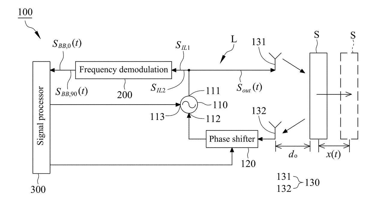
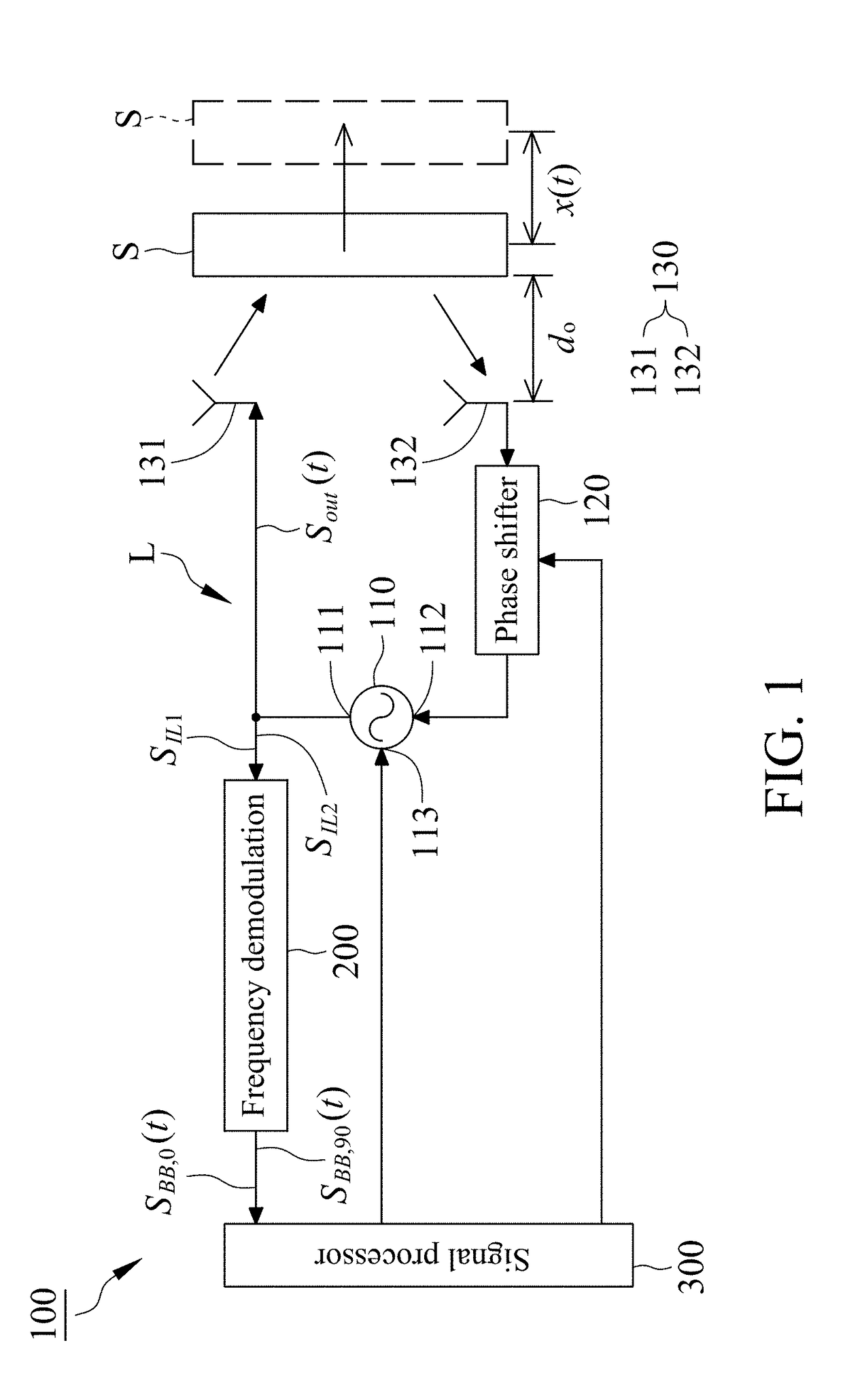
[0014]In the first embodiment, the signal processor 300 demodulates the first frequency demodulation signal SBB,0(t) and the second frequency demodulation signal SBB,90(t) using an arctangent demodulation to obtain a demodulation signal Sdemod(t), and the computing formula of the arctangent demodulation is presented as follows:

Sdemod(t)=tan-1-SBB,0(t)SBB,90(t)=αd(t)=2ωoscc(d0+x(t))

wherein Sdemod(t) is the demodulation signal, SBB,0(t) is the first frequency demodulation signal, SBB,90(t) is the second frequency demodulation signal, αd(t) is the phase variation caused by the displacement of the subject S, c is the speed of light, d0 is the initial distance between the subject S and the transceiver antenna 130, x(t) is the displacement amplitude of the subject S, ωOSC is the initial oscillation frequency of the VCO 110.

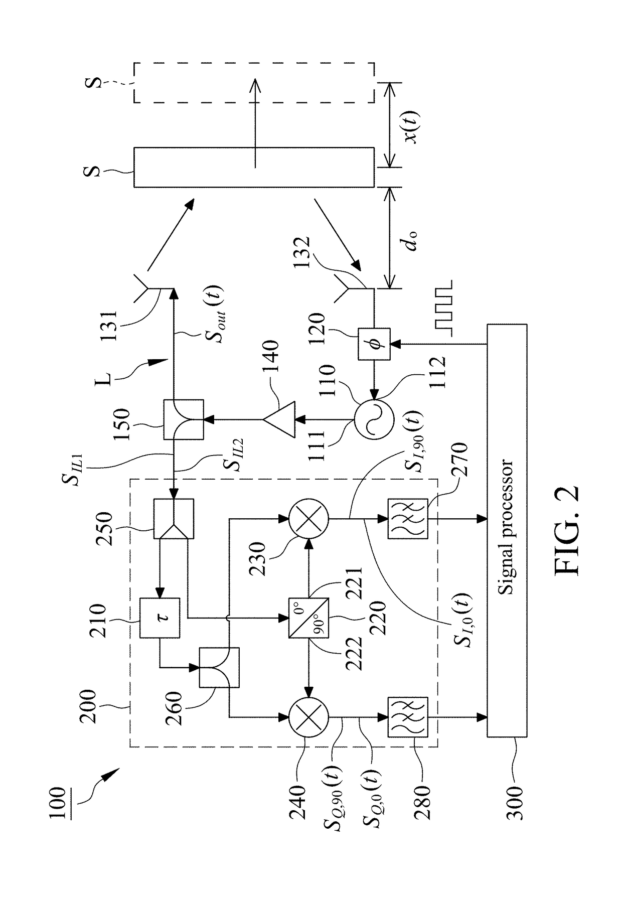
[0015]The oscillation signal Sout(t) is set to operate in the two phase modes with phase difference by the phase shifter 120 in the SIL loop L of the present invention,...

third embodiment

[0024]With reference to FIG. 8, it is a functional block diagram illustrating the present invention, wherein the difference from the first embodiment is there is only one transceiver antenna 130 in the third embodiment. The VCO 110 includes a signal output port 111 and a signal output / injection port 114, wherein the signal output port 111 is electrically connected with the frequency demodulator 200, and the signal output / injection port 114 is electrically connected with the phase shifter 120. The oscillation signal Sout(t) output from the VCO 110 is phase-shifted by the phase shifter 120 and transmitted to the transceiver antenna 130 for radiation, the oscillation signal Sout(t) reflected from the subject S is received by the transceiver antenna 130, phase-shifted by the phase shifter 120 and then injected into the signal output / injection port 114 of the VCO 110 to bring the VCO 110 to the SIL state. In the third embodiment, the oscillation signal Sout(t) is phase-shifted by the pha...


PUM


Abstract

A quadrature self-injection-locked radar utilizes a phase shifter to make a oscillation signal operating in two phase modes, and utilizes a frequency demodulator for frequency demodulation and a signal processor for signal processing to eliminate the nonlinear distortion caused by self-injection locked phenomenon. Therefore, the self-injection locked radar can be applied to more cases for detecting displacement variations with any range.

Description

FIELD OF THE INVENTION[0001]This invention generally relates to a self-injection-locked radar, and more particularly to a quadrature self-injection-locked radar.BACKGROUND OF THE INVENTION[0002]Self-injection-locked (SIL) radar is conventionally applied for detecting important vital signs of biological subject (e.g. respiration and heartbeat). The principle of detection is that SIL radar radiates a radio-frequency (RF) signal to a subject, and the RF signal reflected from the subject is injected into the SIL radar to bring the SIL radar to a SIL state and generate a SIL signal. The displacement of the subject affects the frequency of the RF signal to cause a Doppler effect, for this reason, the SIL signal contains Doppler shift component caused by the displacement of the subject, so that the displacement information of the subject can be obtained by analyzing the SIL signal of the SIL radar in principle. However, when the displacement of the subject is more than 1 / 10 operating wavel...

Claims


Application Information

Patent Timeline
IPC IPC(8): G01S7/35G01S13/32
CPCG01S7/352G01S2007/358G01S13/32G01S7/02G01S13/88G01S13/584G01S7/358H03L7/24
Inventor WANG, FU-KANGHORNG, TZYY-SHENGTANG, MU-CYUN
Owner NAT SUN YAT SEN UNIV
Features
  • Generate Ideas
  • Intellectual Property
  • Life Sciences
  • Materials
  • Tech Scout
  • Unparalleled Data Quality
  • Higher Quality Content
  • 60% Fewer Hallucinations
Learn More