A Geophone Based on PVDF Piezoelectric Nanofibers

A geophone and nanofiber technology, applied in seismic signal receivers, seismology, instruments, etc., can solve the problem that the structure of piezoelectric ceramic geophones is not flexible enough, it is difficult to overcome the increase of capacitance signal distortion, and piezoelectric ceramics are thick and fragile. and other problems, to achieve the effect of improving sensitivity and anti-interference ability, low acoustic impedance and avoiding attenuation

Active Publication Date: 2020-06-19
JILIN UNIV
View PDF4 Cites 0 Cited by
  • Summary
  • Abstract
  • Description
  • Claims
  • Application Information

AI Technical Summary

Problems solved by technology

[0004] However, as disclosed in CN2724018Y "a new type of composite geophone", the existing piezoelectric geophones mostly use piezoelectric ceramics as sensitive elements, which are limited by the thick and fragile defects of piezoelectric ceramics. The device structure is not flexible enough, and the low-frequency cut-off frequency is mostly around 10Hz, which has obvious defects
Moreover, due to the capacitance limitations of piezoelectric ceramics, it is difficult to overcome the contradiction between increasing the capacitance for low-frequency expansion and increasing the capacitance to cause signal distortion
It is worth mentioning that the existing piezoelectric geophone sensing unit often requires the action of elastic components to amplify the vibration response, but the nonlinear distortion of elastic components (such as springs) is also an important cause of signal distortion. Avoiding the adverse effects of spring components under the premise of inductive performance is also an important topic in the research of piezoelectric geophones

Method used


Image

  • A Geophone Based on PVDF Piezoelectric Nanofibers
  • A Geophone Based on PVDF Piezoelectric Nanofibers
  • A Geophone Based on PVDF Piezoelectric Nanofibers

Examples


Embodiment Construction

[0023] The present invention is described in detail below in conjunction with accompanying drawing:

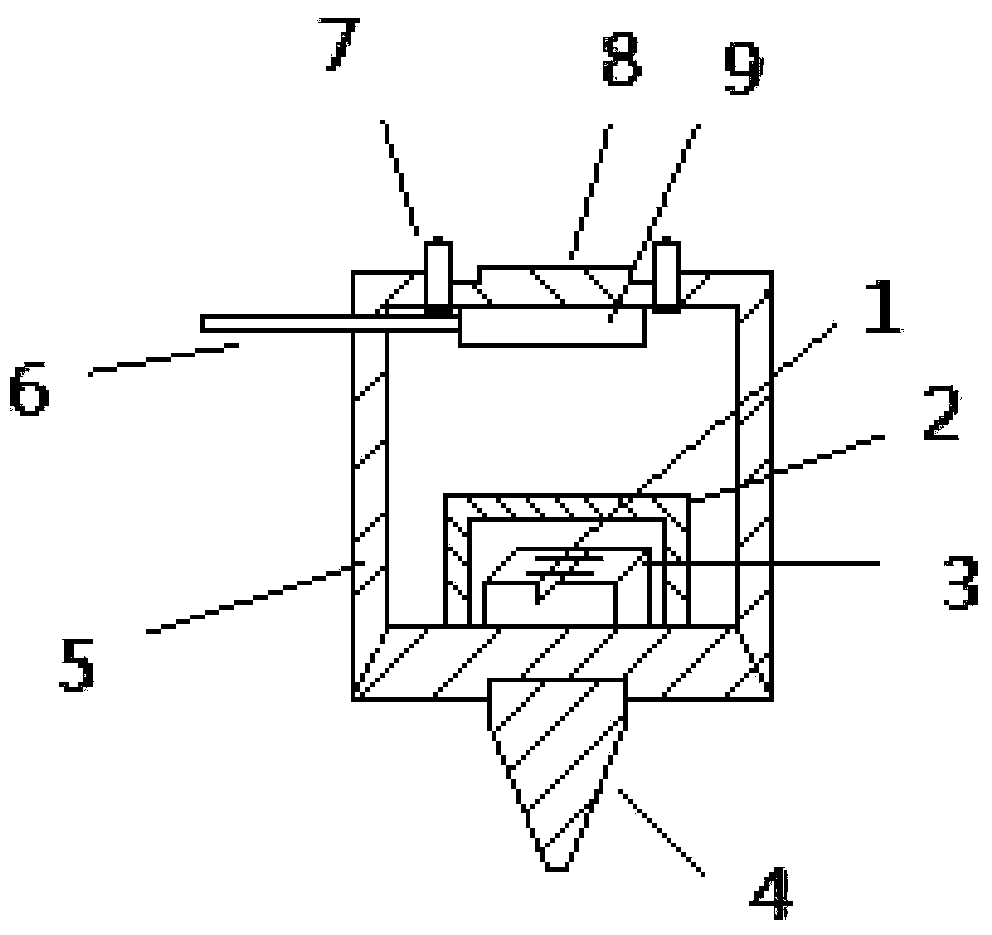
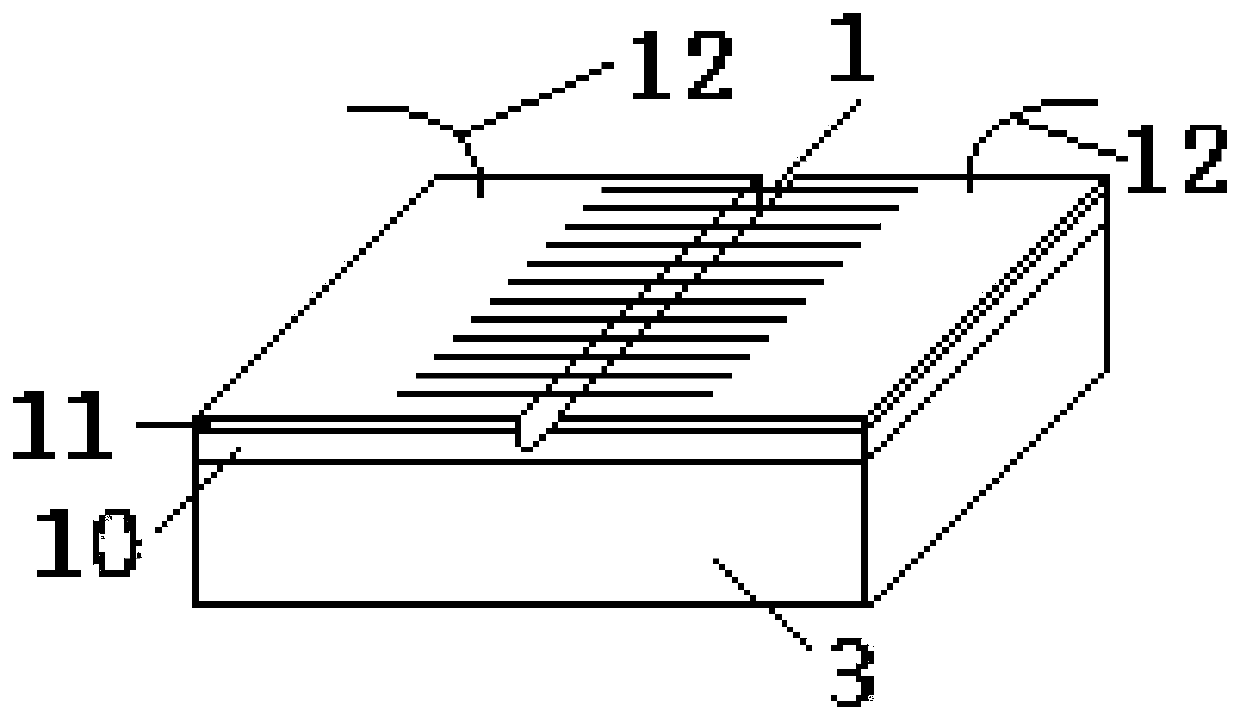
[0024] Such as figure 1 As shown, the seismometer based on PVDF piezoelectric nanofibers of the present invention includes a PVDF nanofiber array 1, a protective cover 2, a base 3, a tail cone 4, a shielding shell 5, an outgoing cable 6, a sealing nut 7, an end Cover 8 and integrated circuit board 9 . PVDF is polyvinylidene fluoride. As an organic piezoelectric material, polyvinylidene fluoride has strong piezoelectric properties and good flexibility.

[0025] Such as figure 1 As shown, the detector includes a rectangular hollow shielding shell 5, and a conical tail cone 4 is arranged on the lower surface of the shielding shell 5. The coccyx 4 is made of metal, and the top surface of the coccyx 4 is provided with screw holes, and the lower surface of the shielding shell 5 is provided with matching screw holes for connecting the coccyx 4 and the lower surface of the shieldin...


PUM

PropertyMeasurementUnit
radiusaaaaaaaaaa

Abstract

The invention provides a seismometer based on PVDF piezoelectric nanofibers. A base is arranged in a shielding shell. A PDMS insulating layer wraps the top surface of the base. A slit is etched in themiddle of the PDMS insulating layer. A layer of metal electrode is coated on the PDMS insulating layer of the two sides of the slit. Multiple PVDF nanofibers form a PVDF nanofibers array. One end ofeach PVDF nanofiber is fixed on the metal electrode on the left side of the slit, and the other end of each PVDF nanofiber is fixed on the metal electrode on the right side of the slit. Each layer ofmetal electrode is connected with a lead. The base is enclosed by a protective sleeve. The shielding shell opening of the upper wall of the shielding shell is covered by an end cap. An integrated circuit board is fixed on the lower surface of the end cap. The two leads penetrate through the protective sleeve to be connected with the integrated circuit board. One end of a lead-out cable is connected with the integrated circuit board, and the other end of the lead-out cable penetrates through the shielding shell and stretches out of the shielding shell. The seismometer based on the PVDF piezoelectric nanofibers is portable and durable, high in sensitivity, high in anti-interference ability and high in reliability.

Description

technical field [0001] The invention belongs to the field of earthquake detection equipment, and relates to a geophone, in particular to a geophone based on PVDF piezoelectric nanofibers. Background technique [0002] Seismic prospecting method is an important means of prospecting mineral resources at present, and it is also widely used in engineering survey and geological disaster prediction and so on. A geophone is a sensor used in seismic exploration to obtain seismic vibration signals and convert the vibration signals into the form required by the signal recording system. Its technical level and performance quality are directly related to the main technical indicators of seismic exploration instruments. [0003] With the development of geophone technology, various forms of geophones such as magnetoelectric, electrochemical, piezoelectric and MEMS digital geophones have emerged. As CN206975230U discloses "a kind of speed-type magnetoelectric high-sensitivity geophone", t...

Claims


Application Information

Patent Timeline
Patent Type & Authority Patents(China)
IPC IPC(8): G01V1/18
CPCG01V1/181G01V2210/144
Inventor 辛毅朱剑锋孙宏帅刘涛徐洋
Owner JILIN UNIV
Why Eureka
Try Eureka