
Open bore field free line magnetic particle imaging system

a free-line magnetic particle and open-bore technology, applied in the field of magnetic particle imaging, can solve the problems of inconvenient clinical use, inability to rotate ffl electronically, and inability to achieve rapid imaging, and achieve the effect of high sensitivity

Active Publication Date: 2018-08-16
ASELSAN ELEKTRONIK SANAYI & TICARET ANONIM SIRKETI
View PDF14 Cites 15 Cited by
  • Summary
  • Abstract
  • Description
  • Claims
  • Application Information

AI Technical Summary

Benefits of technology

The present invention provides an open bore coil system that allows for access to the patient / object for intervention during magnetic resonance imaging (MRI). This system combines the high sensitivity and rapid imaging capabilities of a fully electronically scanned FFL with the potential for using the MPI method for 3D imaging in a clinical environment. Additionally, the system allows for imaging a larger field of view (FOV) while keeping patient safety within acceptable limits.

Problems solved by technology

Although this method has advantages such as low magnetic field level and high sensitivity, it is not suitable for clinical usage as the object should be small and also scanned mechanically.
However, the FFL cannot be rotated electronically and mechanical rotation of the object is necessary for 3D imaging.
Therefore, for a large volume coverage sensitivity and imaging duration are possible issues for these systems.
Nevertheless, the proposed FFL systems rather require coils around the object preventing access, or require mechanical rotation which is not feasible clinically.

Method used


Image

  • Open bore field free line magnetic particle imaging system
  • Open bore field free line magnetic particle imaging system
  • Open bore field free line magnetic particle imaging system

Examples


Embodiment Construction

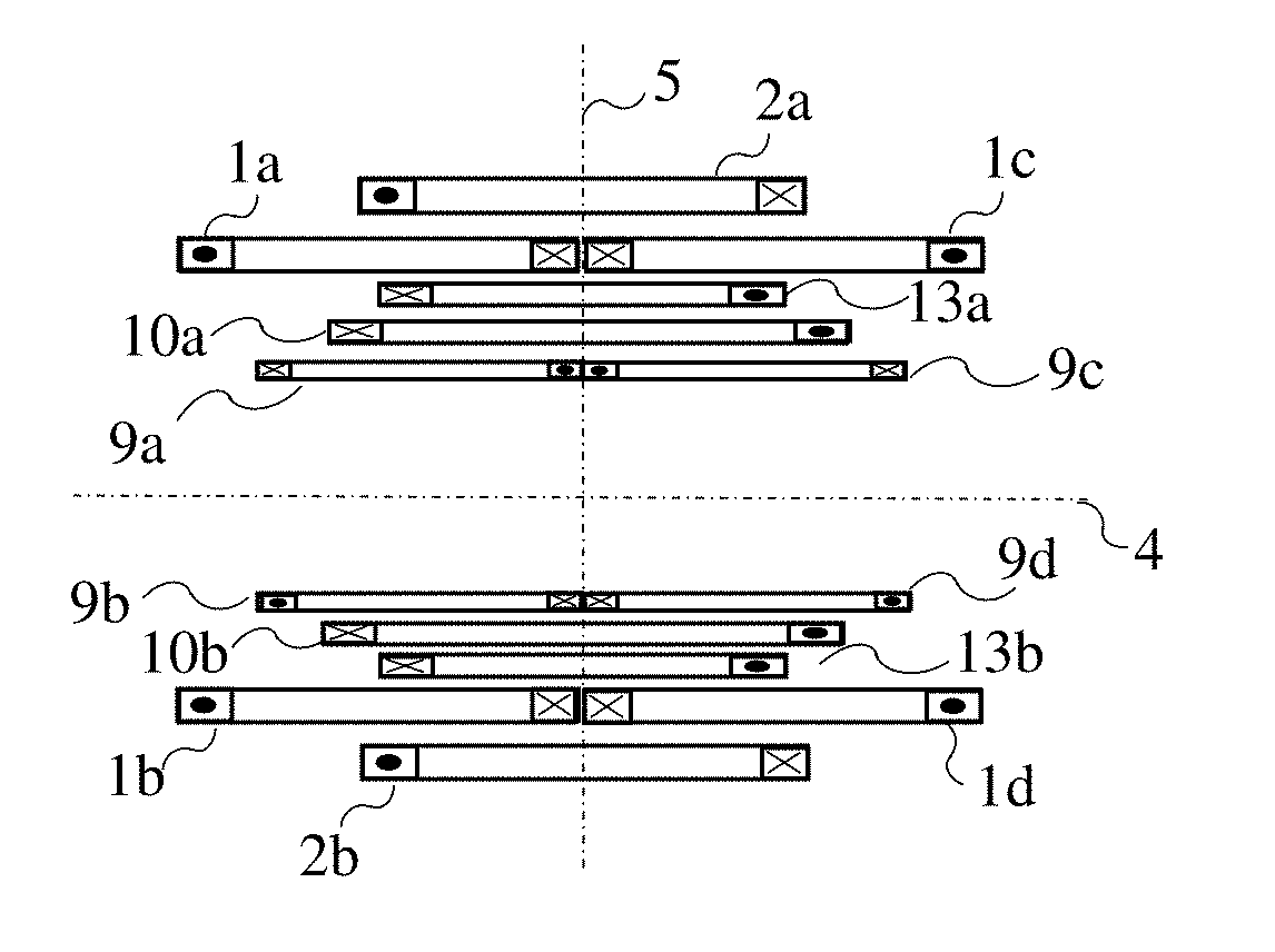
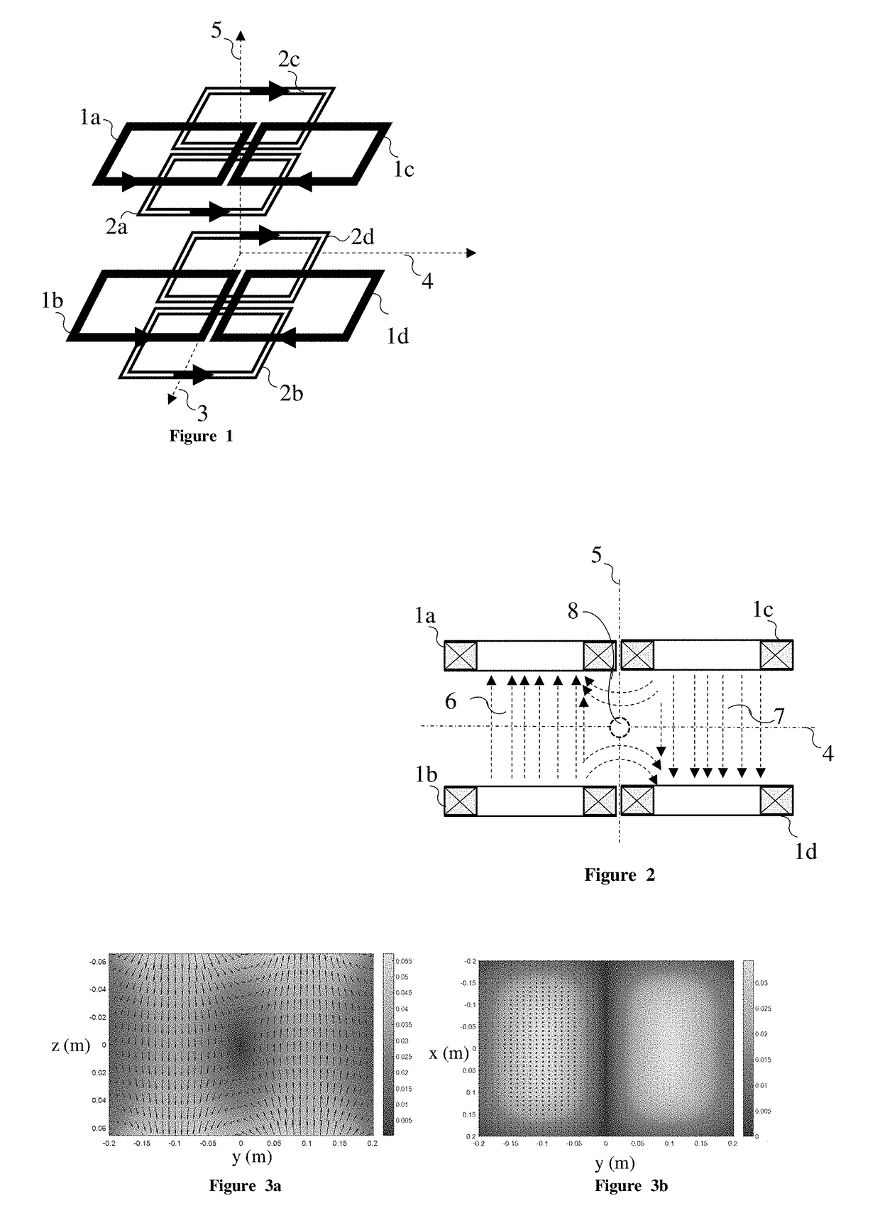
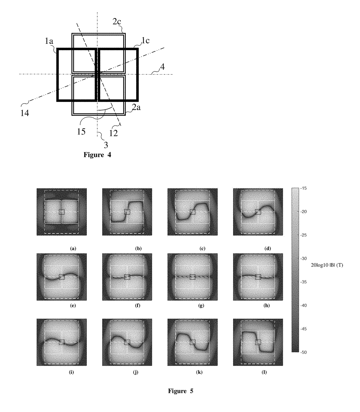
[0043]The selection field coils for the proposed coil system for open bore FFL arrangement consists of 2 coil groups (1, 2). Coils (1a), (1b), (1c), and (1d) form coil group (1) and are fed with currents I1a, I1b, I1c, and I1d, respectively (FIG. 1). Coils (2a), (2b), (2c), and (2d) form coil group (2) and are fed with currents I1a, I2b, I2c, and I2d, respectively. The coils in a coil group are located as coil pairs placed side by side and fed with alternating current directions (FIG. 1). The magnetic field distribution for the coil group (1) is shown in FIG. 2 on the plane generated by the y (4) and z (5) axes (Coil group 2 is not excited in this case). Coils (1a) and (1b) are fed with the same current direction generating a magnetic field in the z-direction (6). Coils (1c) and (1d) are fed with opposite current direction with respect to the (1a-1b) coil pair, generating a magnetic field in the −z direction (7). The x (3) and y (4) components of the magnetic field vanish at the mid...


PUM


Abstract

An open bore coil system enabling electronic steering and rotation of a Field Free Line (FFL) inside a large volume. An FFL is generated by placing two parallel coil pairs (fed with alternating current directions) side by side. Using two of these coil groups, the FFL can be rotated in the plane perpendicular to the coil axes. The FFL can be translated in the rotation plane of the FFL using a coil pair placed on the same axis with the other coils. It can also be translated in the perpendicular plane by asymmetrical coil excitation. As all the coils in the system are parallel, the imaged object can be reached from the sides during imaging.

Description

FIELD AND BACKGROUND OF THE INVENTION[0001]The present invention relates generally to the field of Magnetic Particle Imaging, and in particular to an open bore coil system enabling electronic steering and rotation of a Field Free Line (FFL) inside a large volume.[0002]Magnetic Particle Imaging (MPI) is an imaging method, which images the concentration of Super Paramagnetic Iron Oxide (SPIO) particles inside a volume of interest. The SPIO nanoparticles can be injected intravenously, or administered orally to the patient / object. It has several potential uses for medical imaging such as angiography, stem cell tracking, and tumor detection.[0003]In the MPI method, the object is placed inside a magnetic field, which includes a field free region (FFR). In this region, the magnetic field strength is very low so that if there are SPIO nanoparticles in this region, their magnetization is not saturated. (i.e. their magnetization can be increased or decreased parallel to the applied magnetic f...

Claims


Application Information

Patent Timeline
Patent Type & Authority Applications(United States)
IPC IPC(8): G01R33/56A61B5/05G01R33/38G01R33/563
CPCG01R33/5601G01R33/5635G01R33/3806A61B5/0515G01R33/1276G01R33/36G01R33/34061A61B5/0046
Inventor TOP, CAN BARISGUVEN, HUSEYIN EMRE
Owner ASELSAN ELEKTRONIK SANAYI & TICARET ANONIM SIRKETI
Learn More