Goa drive circuit and embedded type touch display panel

a drive circuit and display panel technology, applied in the field of display panel technology, can solve the problem of delay of the touch scan signal outputted to the embedded touch display panel, and achieve the effect of promoting detection accuracy and reducing the delay of the touch scan signal

Active Publication Date: 2018-08-16
WUHAN CHINA STAR OPTOELECTRONICS TECH CO LTD
View PDF2 Cites 6 Cited by
  • Summary
  • Abstract
  • Description
  • Claims
  • Application Information

AI Technical Summary

Benefits of technology

[0023]In comparison with prior art, the nth level GOA unit of the GOA drive circuit according to the present invention comprises the output end pull down unit and the output control unit. Both the output end pull down unit and the output control unit are employed to control the signal outputted by the output end of the nth level GOA unit. One end of the output end pull down unit is electrically coupled to a first end point L, and the first end point L is loaded with a first signal, and one end of the output control unit is electrically coupled to a nth clock signal, and as the embedded touch display panel enters signal interrupt and performs a touch scan stage, the output control unit is off to cut off an output path that the nth clock signal outputs to the output end, and the output end pull down unit is on to output the first signal through an output end of the GOA unit, wherein as the embedded touch display panel enters signal interrupt and performs the touch scan stage, the first signal is a signal consistent with a touch scan signal of the embedded touch display panel. Accordingly, the signals of the output ends of the GOA units of all levels are consistent with the scan touch signal to decrease the delay of the touch scan signal, and thus to promote the detection accuracy as the embedded touch display panel detects the user's touch operation.

Problems solved by technology

Generally, the touch scan signal is a pulse signal different from the constant voltage level signal, and ultimately results in the delay of the touch scan signal outputted to the embedded touch display panel.

Method used


Image

  • Goa drive circuit and embedded type touch display panel
  • Goa drive circuit and embedded type touch display panel
  • Goa drive circuit and embedded type touch display panel

Examples


Embodiment Construction

[0030]Embodiments of the present invention are described in detail with the technical matters, structural features, achieved objects, and effects with reference to the accompanying drawings as follows. It is clear that the described embodiments are part of embodiments of the present invention, but not all embodiments. Based on the embodiments of the present invention, all other embodiments to those of ordinary skill in the premise of no creative efforts obtained, should be considered within the scope of protection of the present invention.

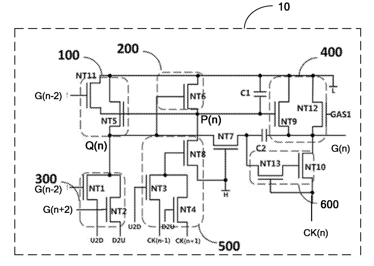
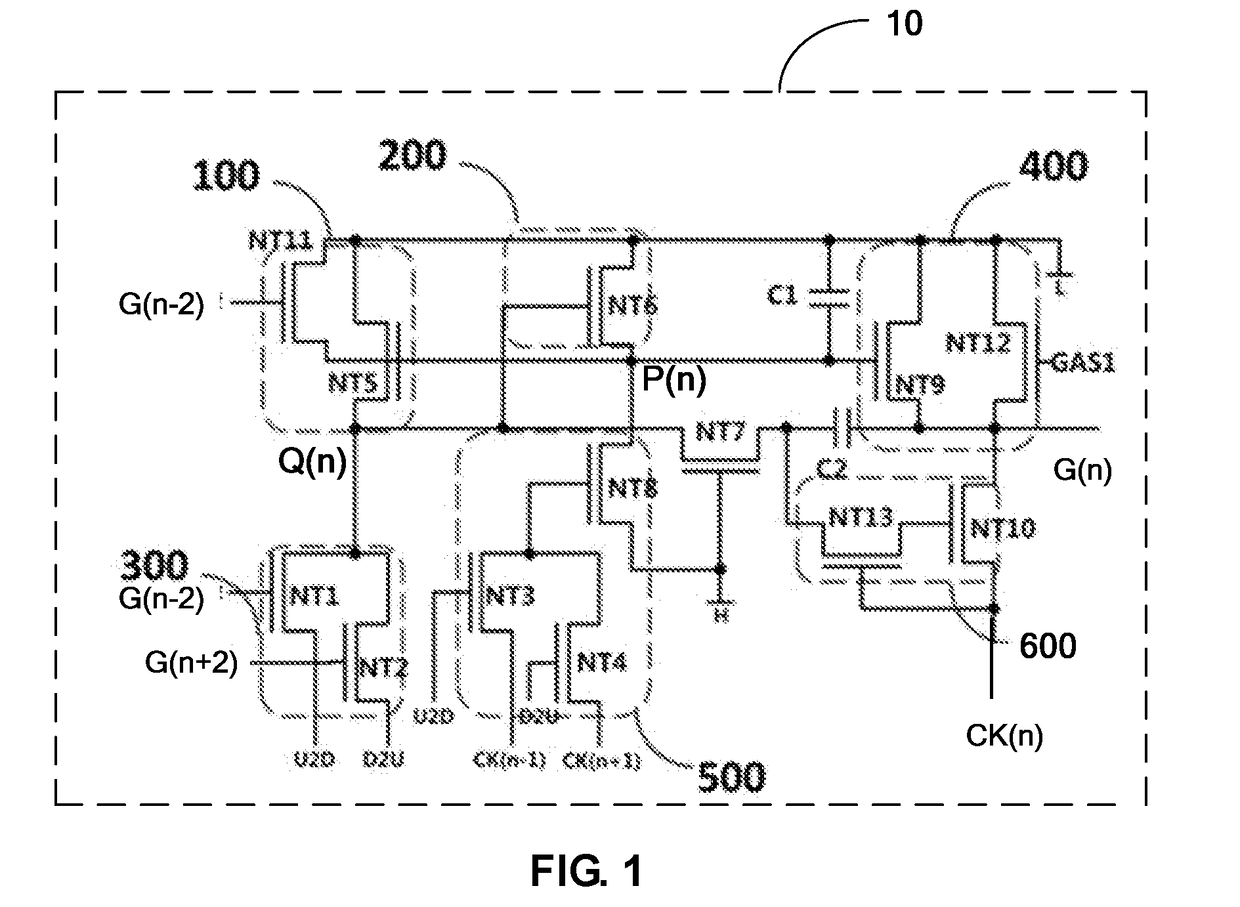
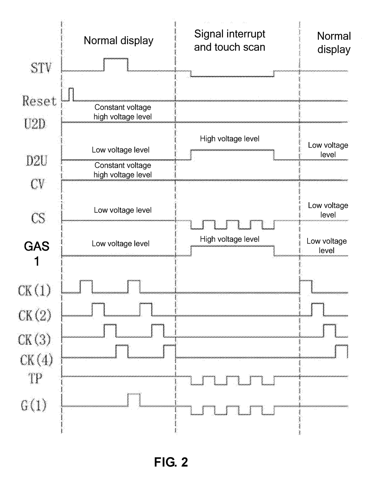
[0031]Please refer to FIG. 1 and FIG. 2. FIG. 1 is a circuit diagram of one preferred embodiment of a nth level GOA unit in a GOA drive circuit according to the present invention; FIG. 2 is a sequence diagram as the GOA drive circuit shown in FIG. 1 perform forward scan; FIG. 3 is a drive circuit diagram of one pixel in an embedded touch display panel which is applied with a GOA drive circuit according to the present invention. The GOA drive circui...


PUM

PropertyMeasurementUnit
voltageaaaaaaaaaa
voltage levelaaaaaaaaaa
constant voltageaaaaaaaaaa

Abstract

The present invention provides a GOA drive circuit and embedded type touch display panel. The GOA drive circuit comprises GOA units cascade coupled in multilevel, the nth level GOA unit comprises an output end pull down unit and an output control unit, both the output end pull down unit and the output control unit are employed to control a signal outputted by an output end of the nth level GOA unit, and one end of the output end pull down unit is coupled to a first end point, the first end point is loaded with a first signal, and one end of the output control unit is coupled to a nth clock signal, and as the embedded touch display panel enters signal interrupt and performs a touch scan, the output control unit is off to cut off an output path that the nth clock signal outputs to the output end.

Description

CROSS REFERENCE[0001]This application claims the priority of Chinese Patent Application No. 201610761256.3, entitled “GOA drive circuit and embedded type touch display panel”, filed on Aug. 29, 2016, the disclosure of which is incorporated herein by reference in its entirety.FIELD OF THE INVENTION[0002]The present invention relates to a display panel technology field, and more particularly to a GOA drive circuit and an embedded type touch display panel.BACKGROUND OF THE INVENTION[0003]The Liquid Crystal Display (LCD) possesses advantages of thin body, power saving and no radiation to be widely used in many application scope. The common liquid crystal display devices can be the liquid crystal television, the mobile phone, the Personal Digital Assistant (PDA), the digital camera or the notebook.[0004]Gate Driver on Array (GOA) technology, i.e. the array substrate row driving technology is to utilize the array manufacture process of the Thin Film Transistor (TFT) liquid crystal display...

Claims


Application Information

Patent Timeline
Patent Type & Authority Applications(United States)
IPC IPC(8): G02F1/1333G09G3/36G02F1/133G06F3/041
CPCG02F1/13338G09G3/36G02F1/13306G06F3/0412G06F3/044G09G3/3677G09G3/3648G09G2310/0286G06F3/04184G06F3/04166
Inventor CAO, SHANGCAODAI, RONGLEI
Owner WUHAN CHINA STAR OPTOELECTRONICS TECH CO LTD
Why Eureka
Try Eureka