Power supply system for vehicle

a power supply system and vehicle technology, applied in hybrid vehicles, battery/fuel cell control arrangements, transportation and packaging, etc., can solve the problems of reducing the fuel efficiency of the vehicle as a whole, the battery performance of the lithium-ion storage battery having a high regeneration capability will not be satisfactorily used, and the potential of the lithium-ion storage battery with a lower potential will not be sufficiently charged

Inactive Publication Date: 2018-08-16
HONDA MOTOR CO LTD
View PDF14 Cites 11 Cited by
  • Summary
  • Abstract
  • Description
  • Claims
  • Application Information

AI Technical Summary

Benefits of technology

[0024]In the power supply system for a vehicle according to one or some of exemplary embodiments of the invention, the first and second power storage devices are arranged in parallel to the power generator, the charging circuit of the second power storage device in which the second power storage device and the power generator are connected is connected to the first power storage device via the first switch, and the open circuit voltage of the first power storage device is set to be higher than the open circuit voltage of the second power storage device. In the power supply system for a vehicle, when the regenerative power generation of the power generator is started, the first switch is turned on and the simultaneous charging of the first and second power storage devices is started. Accordingly, a generated current is supplied from the power generator to the first and second power storage devices and thus the first and second power storage devices are simultaneously charged. Here, when the simultaneous charging of the first and second power storage devices is continuously performed as described above, the first power storage device having a higher potential is changed from charging to discharging. In the power supply system for a vehicle according to one or some of exemplary embodiments of the invention, by turning off the first switch at the timing determined based on the charging state of the first power storage device while the simultaneous charging is being performed, the simultaneous charging can be switched to the preferential charging of the second power storage device before the first power storage device is changed from charging to discharging. Accordingly, it is possible to charge the first power storage device to a certain extent while the second power storage device is prevented from having a poor state of charge. Since an opportunity to drive the power generator using an engine while the vehicle is traveling and to forcibly charge the second power storage device can be reduced by preventing the second power storage device from having a poor state of charge, it is possible to improve fuel efficiency of the vehicle as a whole.
[0025]In the power supply system for a vehicle according to one or some of exemplary embodiments of the invention, the preferential charging of the first power storage device is started by turning off the second switch and turning on the first switch at the timing which is determined based on the charging state of the second power storage device after the simultaneous charging is switched to the preferential charging of the second power storage device. That is, in the power supply system for a vehicle according to one or some of exemplary embodiments of the invention, the second power storage device is preferentially charged and then the first power storage device is charged when there is room to spare. Accordingly, when the regenerative power generation is prolonged, it is possible to additionally charge the first power storage device while preferentially charging the second power storage device.
[0027]The generated current in the regenerative power generation decreases with a decrease in the speed of the vehicle and a decrease in the rotation speed of the power generator. Accordingly, the generated current decreases, the voltage of the junction connected to the first power storage device in the charging circuit decreases, and the first power storage device is switched from charging to discharging. Therefore, in the power supply system for a vehicle according to one or some of exemplary embodiments of the invention, when the voltage of the junction becomes equal to or lower than the open circuit voltage of the first power storage device while the simultaneous charging is being performed, it is possible to minimize discharging of the first power storage device during the regenerative power generation by turning off the first switch.
[0027]The generated current in the regenerative power generation decreases with a decrease in the speed of the vehicle and a decrease in the rotation speed of the power generator. Accordingly, the generated current decreases, the voltage of the junction connected to the first power storage device in the charging circuit decreases, and the first power storage device is switched from charging to discharging. Therefore, in the power supply system for a vehicle according to one or some of exemplary embodiments of the invention, when the voltage of the junction becomes equal to or lower than the open circuit voltage of the first power storage device while the simultaneous charging is being performed, it is possible to minimize discharging of the first power storage device during the regenerative power generation by turning off the first switch.
[0028]In the power supply system for a vehicle according to one or some of exemplary embodiments of the invention, the first and second power storage devices are arranged in parallel to the power generator, the charging circuit of the second power storage device in which the second power storage device and the power generator are connected is connected to the first power storage device via the first switch, and the open circuit voltage of the first power storage device is set to be higher than the open circuit voltage of the second power storage device. In the power supply system for a vehicle, the regenerative power generation is started while the first switch is turned off and the preferential charging of the second power storage device is started. Accordingly, a generated current is supplied from the power generator to the second power storage device and thus the second power storage device is charged. At this time, the voltage of the junction connected to the first power storage device in the charging circuit of the second power storage device and the open circuit voltage of the first power storage device are acquired, and the first switch is turned on and the simultaneous charging of the first and second power storage devices is performed at the timing determined based on the voltage of the junction while the generated current is supplied to the second power storage device and the open circuit voltage of the first power storage device as described above. In a case in which the first and second power storage devices are connected to the power generator and the simultaneous charging thereof is performed, the first power storage device may not be charged but may be discharged even by turning on the first switch when the generated current from the power generator is small and the voltage of the junction is lower than the open circuit voltage of the first power storage device. In the power supply system for a vehicle according to one or some of exemplary embodiments of the invention, in the regenerative power generation, by preferentially charging the second power storage device and then determining the time at which the simultaneous charging is started using the voltage of the junction and the voltage of the first power storage device, it is possible to start the simultaneous charging while discharging of the first power storage device is prevented. Accordingly, it is possible to charge the first power storage device to a certain extent while the second power storage device is prevented from having a poor state of charge. Since opportunities to drive the power generator using an engine while the vehicle is traveling and to forcibly charge the second power storage device can be reduced by preventing the second power storage device from having a poor state of charge, it is possible to improve fuel efficiency of the vehicle as a whole.
[0029]The generated current in the regenerative power generation decreases with a decrease in the speed of the vehicle and a decrease in the rotation speed of the power generator. Accordingly, when the generated current decreases and the voltage of the junction decreases, the first power storage device is switched from charging to discharging. Therefore, in the power supply system for a vehicle according to one or some of exemplary embodiments of the invention, when the voltage of the junction becomes equal to or lower than the open circuit voltage of the first power storage device while the first power storage device is being charged by turning on the first switch, it is possible to minimize discharging of the first power storage device during the regenerative power generation by turning off the first switch.

Problems solved by technology

That is, since a timing at which charging of the lithium-ion storage battery ends in the simultaneous charging is determined depending on the discharging state of the lead storage battery regardless of the state of the lithium-ion storage battery, there is concern that the lithium-ion storage battery having a lower potential will not be sufficiently charged and battery performance of the lithium-ion storage battery having high regeneration capability will not be satisfactorily used because discharging of the lead storage battery has been prevented.
That is, when the lithium-ion storage battery has a poor state of charge during travel, there is concern that the power generator needs to be driven with an engine to charge the lithium-ion storage battery and thus fuel efficiency of the vehicle as a whole will decrease.[Patent Document 1] Japanese Patent No. 5889750

Method used


Image

  • Power supply system for vehicle
  • Power supply system for vehicle
  • Power supply system for vehicle

Examples


first embodiment

[0030]Hereinafter, a first embodiment of the invention will be described with reference to the accompanying drawings.

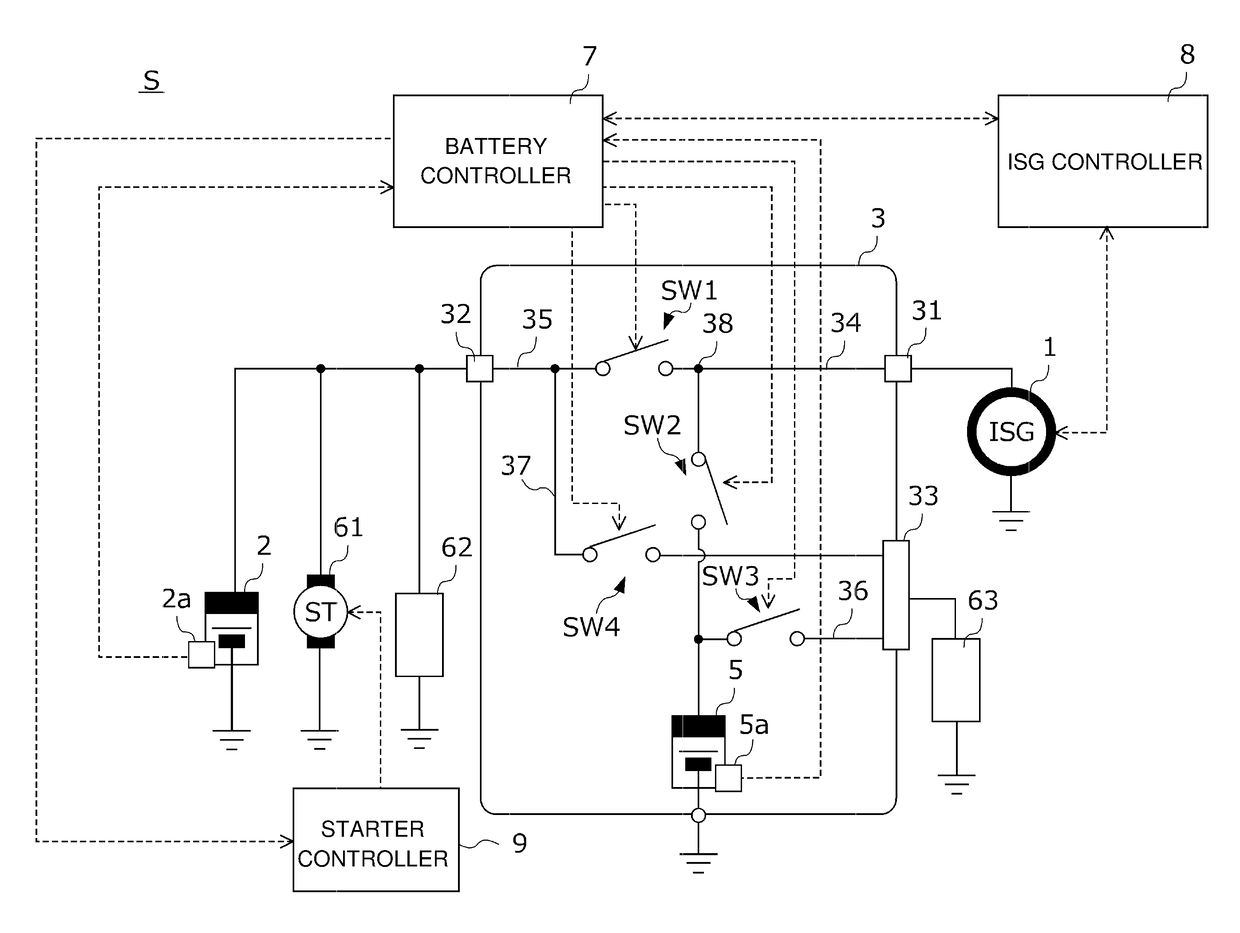
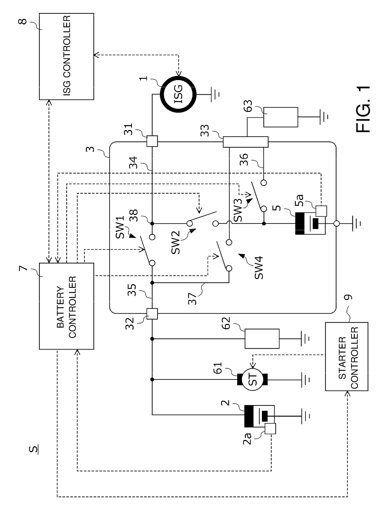
[0031]FIG. 1 is a diagram illustrating a configuration of a power supply system S according to this embodiment. The power supply system S is for a vehicle and is mounted in a vehicle which is not illustrated and which includes an engine as a power train. The power supply system S supplies power to various electric loads mounted in the vehicle or is charged with power which is generated using a power generator mounted in the vehicle.

[0032]The power supply system S includes a motor generator 1 serving as a power generator, a first battery 2 serving as a first power storage device, a battery module 3 including a second battery 5 serving as a second power storage device, and a battery controller 7 that controls the battery module 3.

[0033]The motor generator 1 is connected to a crank shaft of an engine which is not illustrated via a power transmission mechanism such as a b...

second embodiment

[0081]A second embodiment of the invention will be described below with reference to the accompanying drawings.

[0082]FIG. 5 is a flowchart illustrating a specific process flow of switch control in a power supply system according to this embodiment. The power supply system according to this embodiment is different from the power supply system according to the first embodiment, in that a voltage sensor that detects the voltage of the junction is additionally provided and a part of the specific process flow of the switch control is modified, and both are the same in the other configurations. The processes of S31 and S36 to S42 among the processes of S31 to S41 illustrated in FIG. 5 are the same as the processes of S11 and S15 to S21 illustrated in FIG. 4 and thus detailed description thereof will not be repeated.

[0083]When the determination result of S31 is YES, that is, when the simultaneous charging of the first and second batteries is currently performed, the battery controller acqu...

third embodiment

[0089]A third embodiment of the invention will be described below with reference to the accompanying drawings.

[0090]FIG. 6 is a flowchart illustrating a specific process flow of charging control the first and second batteries in a power supply system according to this embodiment. The power supply system according to this embodiment is different from the power supply system according to the first embodiment, in that a voltage sensor that detects the voltage of the junction is additionally provided and a part of the specific process flow of the charging control is modified, and both are the same in the other configurations.

[0091]In S51, the battery controller determines whether it is immediately after the regenerative power generation is started. When the determination result of S51 is YES, the battery controller turns on the second switch with the first switch turned off and starts the preferential charging of the second battery (see S52).

[0092]In the power supply system according to...


PUM


Abstract

A power supply system is provided. The power supply system includes a motor generator capable of performing regenerative power generation when a vehicle decelerates, first and second batteries connected in parallel to the motor generator, a first switch for connecting or disconnecting a first power supply line connecting the second battery and the motor generator to or from the first battery, and a second switch disposed in the first power supply line. An open circuit voltage of the first battery is controlled to be higher than that of the second battery. The power supply system turns on the first and second switches and starts simultaneous charging of the first and second batteries when regenerative power generation is started, and then turns off the first switch and starts preferential charging of the second battery at a timing based on a charging current indicating a charging state of the first battery.

Description

CROSS REFERENCE TO RELATED APPLICATIONS[0001]This application claims the priority benefit of Japanese Patent Application No. 2017-026119, filed on Feb. 15, 2017. The entirety of the above-mentioned patent application is hereby incorporated by reference herein and made a part of this specification.BACKGROUND OF THE INVENTIONField of the Invention[0002]The disclosure relates to a power supply system for a vehicle. More particularly, the disclosure relates to a power supply system for a vehicle including a power generator that can generate power while the vehicle is traveling and two storage batteries that are connected to the power generator.Description of Related Art[0003]In a power supply system for a vehicle, power generated by a power generator while the vehicle is traveling is stored in a power storage device such as a secondary battery or a capacitor and is supplied to various electric loads (for example, a traveling motor for causing the vehicle to travel or auxiliary machines ...

Claims


Application Information

Patent Timeline
Patent Type & Authority Applications(United States)
IPC IPC(8): H02J7/14H02J7/16B60K6/26B60W20/00
CPCH02J7/1423H02J7/16B60K6/26B60W20/00B60K2006/268Y10S903/906B60Y2200/92B60Y2300/91B60W2710/244B60R16/033H02J7/00B60W10/08B60W10/26B60W20/14B60L58/20H02J7/14B60L7/18B60L2240/547B60L2240/80B60L58/13Y02T10/70H02J7/0048
Inventor KOIZUMI, YUKI
Owner HONDA MOTOR CO LTD
Why Eureka
Try Eureka