
Sensor arrangement with RFID

Active Publication Date: 2018-08-23
SFS GRP INT AG
View PDF2 Cites 2 Cited by
  • Summary
  • Abstract
  • Description
  • Claims
  • Application Information

AI Technical Summary

Benefits of technology

The invention is a fastening element with an RFID transponder and sensor system for roof structures. This allows for easy placement of sensors at specific locations without needing to add extra steps. It also prevents damage to the insulation layers or roof membrane and makes it easy to train or change to a new system. The fastening elements are already installed in high-loaded roof areas, so they can be used without needing to plan. The sensor arrangement can be distributed on the fastening element or attached close to the tip, improving reception and transmission conditions. The grommet can also be attached in a detachable manner for flexibility in sensor placement. Overall, this invention simplifies the installation process and improves the accuracy and reliability of sensor readings on roof structures.

Problems solved by technology

The disadvantage of this solution is that these sensors with RFID transponder have to be laid separately, e.g. below or between various layers of the building envelope.

Method used


Image

  • Sensor arrangement with RFID
  • Sensor arrangement with RFID
  • Sensor arrangement with RFID

Examples


Embodiment Construction

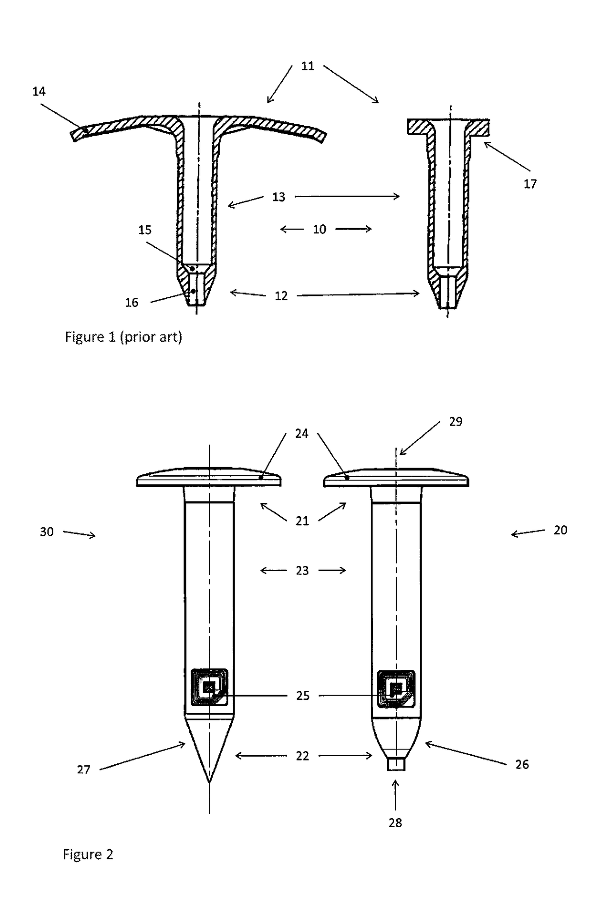
[0029]FIG. 1 shows a fastening element 10 according to the prior art in two variants. In the design on the left, the head 11 is constructed as an extensive washer 14, which, as shown in FIG. 4, can bear against an insulation layer of a roof covering and then distribute the vertical tensile forces. The variant in FIG. 1 on the right only has a stop collar 17, which can be combined with various washers. A tubular sleeve 13 connects the head 11 to a conical tip 12 in each case, as shown in section. The sleeve narrows in the cone in feature 15 and merges into an axial opening 16.

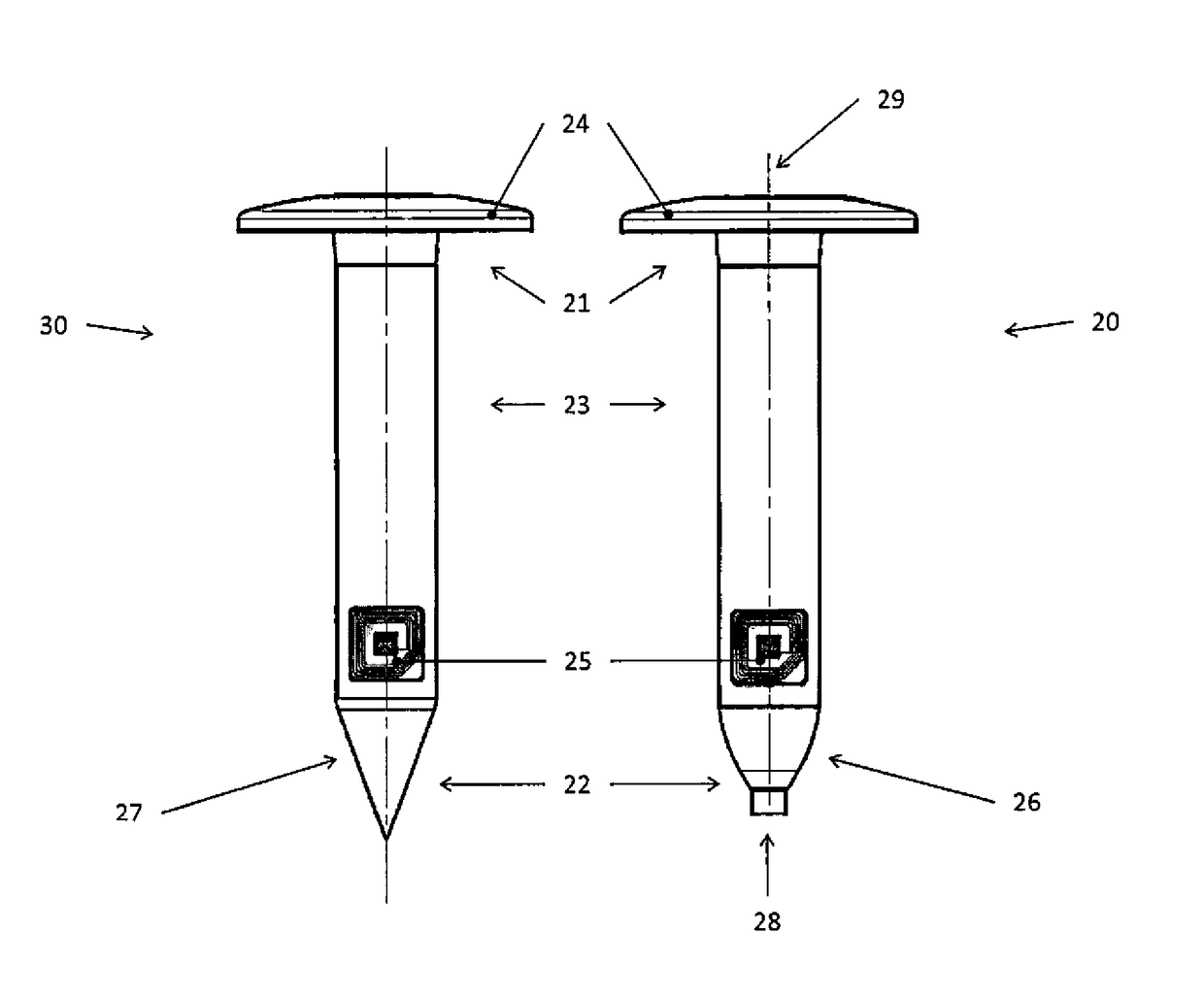
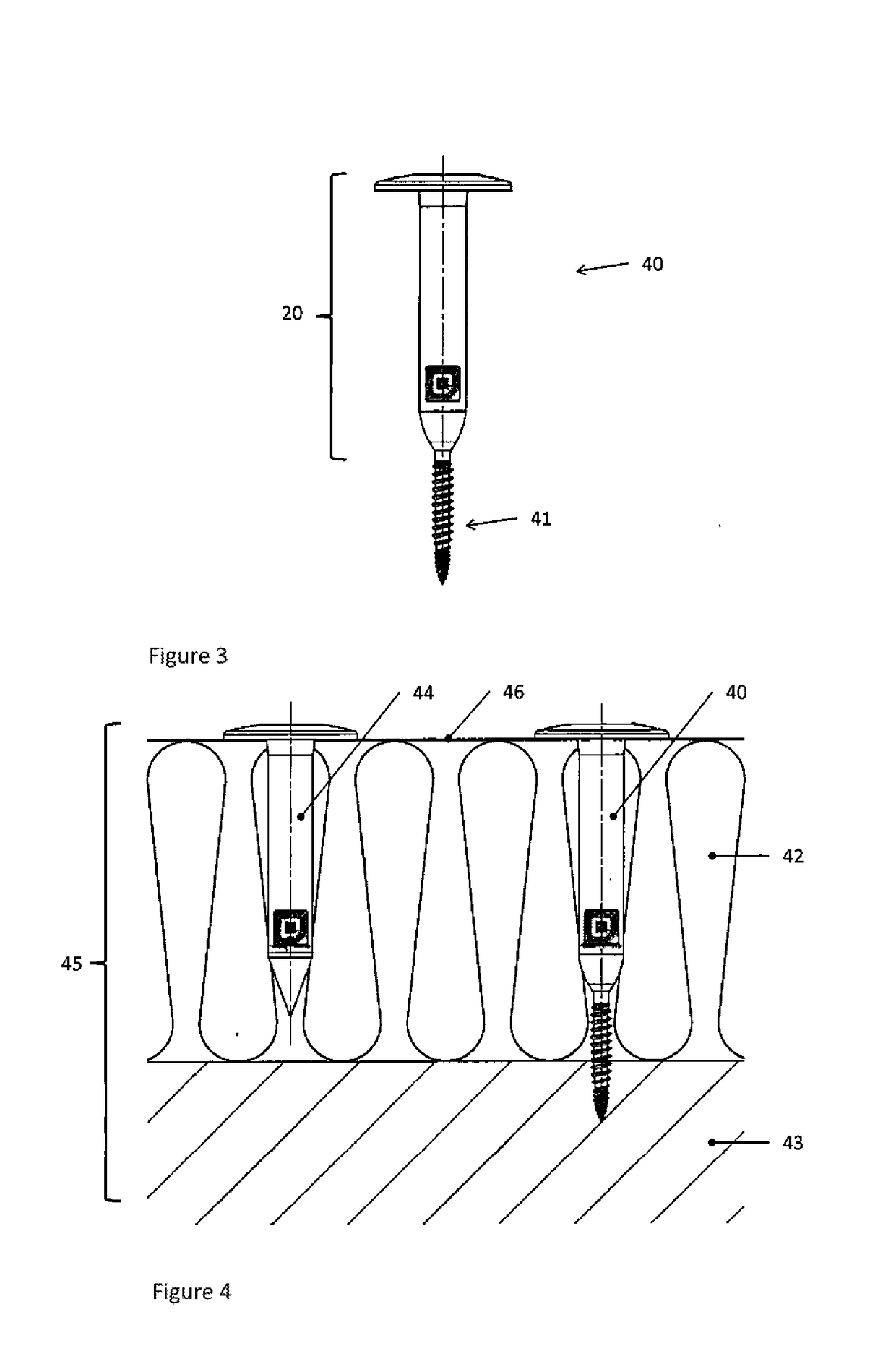
[0030]FIG. 2 shows the two preferred main variants of the grommet according to the invention. The variant in FIG. 2 on the right corresponds to a grommet 20, the purpose of which includes the function as part of a fastening element, as illustrated in FIG. 4 (“fastening grommet”). The variant of a grommet 30, on the left in the image, corresponds to the pure plug-in element without fastening function (“plug-in gr...


PUM


Abstract

A grommet (20, 30) as part of a fastening element for a building envelope essentially comprises a head (21), a tip (22) and a sleeve (23) therebetween, wherein the head (21) is essentially constructed as an extensive washer (24), the central hole of which is adjoined by the tubular sleeve (23). The tip (22) narrows essentially in a conical or tapered manner to a smaller diameter. The grommet (20, 30) has a sensor arrangement (25), with at least one RFID transponder with antenna and a sensor operatively connected to the transponder.

Description

INCORPORATION BY REFERENCE[0001]The following documents are incorporated herein by reference as if fully set forth: European Patent Application No. 17157462.7, filed Feb. 22, 2017.FIELD OF THE INVENTION[0002]The present invention is concerned with a sensor arrangement in building envelopes, particularly for measuring environmental parameters and detecting building damage.BACKGROUND[0003]In construction, highly complex building envelopes are used increasingly, which consist of multi-layered, functionally adapted layers. In this case, both in the outer wall and roof structures, combinations of thermal insulation layers, supporting / fixing elements, and protective membranes against environmental influences such as wind, rain, snow, etc. are used. Combinations of mineral fibre products, foams, plastic films and punctiform fastening elements therefor are conventional today in the case of roof structures specifically.[0004]Keeping such building envelopes permanently steam- and water-tight ...

Claims


Application Information

Patent Timeline
IPC IPC(8): G06K19/077G01D11/24
CPCG06K19/07773G01D11/245G01D11/00E04B1/7633F16B13/00F16B13/124G01N33/383
Inventor GASSER, DANIELBLUM, KURT
Owner SFS GRP INT AG
Learn More