Wheel sensor

a technology of sensor and wheel, applied in the direction of acceleration measurement using interia force, inflated body pressure measurement, instruments, etc., can solve the problems of insufficient amount of acceleration data to be transmitted, and more data processing needs to be done internally, so as to achieve stable angle, reduce noise, and save time and energy

Active Publication Date: 2018-08-30
MELEXIS TECH NV
View PDF0 Cites 16 Cited by
  • Summary
  • Abstract
  • Description
  • Claims
  • Application Information

AI Technical Summary

Benefits of technology

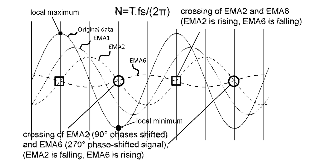
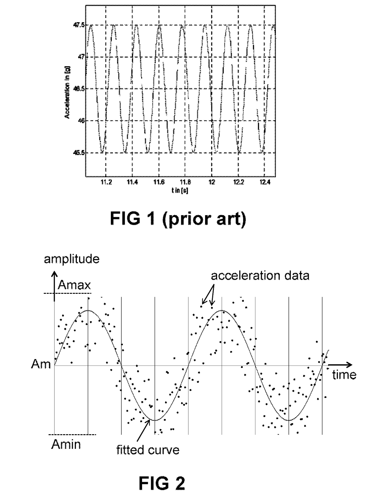
[0026]In contrast to “curve fitting” or other minimization techniques, which are techniques that require a powerful processor and consume a lot of time and energy, and therefore need to be done outside of the sensor device, the inventors have found that it is possible to obtain a very stable angle (robust against noise) by using said digital filtering techniques, based on at least two EMA's.
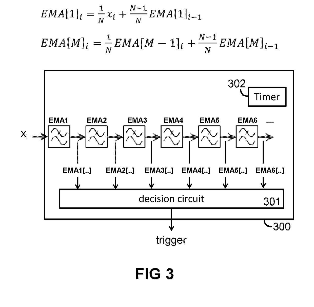
[0027]It is a major advantage of using at least two and preferably less than seven EMA-filters connected in series, inter alia because such a filter can be implemented on a relatively simple processor, and requires only a limited number of operations (e.g. in the order of only two multiplications and one addition per additional sample), and requires only very limited memory resources. This is advantageous in terms of silicon area (thus chip cost) as well as power consumption (lifetime of battery powered application).
[0028]It is an advantage that a series of EMA-filters, when provided with noisy data at the input, can effectively be used for filtering the mechanical noise encountered in this kind of application.
[0029]It is a major advantage of such a filter that it provides a substantially constant phase shift, which is largely insensitive to the frequency at which the acceleration sensor is sampled.

Problems solved by technology

While it would be technically possible to associate the position of each wheel (e.g. front left, front right, rear left, rear right) by manually entering a unique ID in a controller of the vehicle (e.g. a board computer), a problem occurs when wheels are replaced, for example between seasons.
TPMS devices are typically battery powered, and it is a major challenge to meet low power consumption such that a single battery is capable of operating the TPMS device (mounted on the wheel) for a period of e.g. 10 years, while being capable of measuring the tire pressure and transmitting acceleration related data (during a certain time-window after the car is moving) for allowing auto-localization.
These devices have the disadvantage that a sufficient amount of acceleration data needs to be transmitted, but have the advantage that the devices do not need to actually process the data (apart from packaging or wrapping the data in a data packet, optionally providing a time-stamp, and the like).
These devices have the disadvantage that more data processing needs to be done internally, but have the advantage that the devices can transmit less data.

Method used


Image

  • Wheel sensor
  • Wheel sensor
  • Wheel sensor

Examples


Embodiment Construction

[0088]The present invention will be described with respect to particular embodiments and with reference to certain drawings but the invention is not limited thereto but only by the claims. The drawings described are only schematic and are non-limiting. In the drawings, the size of some of the elements may be exaggerated and not drawn on scale for illustrative purposes. The dimensions and the relative dimensions do not correspond to actual reductions to practice of the invention.

[0089]Furthermore, the terms first, second and the like in the description and in the claims, are used for distinguishing between similar elements and not necessarily for describing a sequence, either temporally, spatially, in ranking or in any other manner. It is to be understood that the terms so used are interchangeable under appropriate circumstances and that the embodiments of the invention described herein are capable of operation in other sequences than described or illustrated herein.

[0090]Moreover, t...


PUM

PropertyMeasurementUnit
speedaaaaaaaaaa
speedaaaaaaaaaa
speedaaaaaaaaaa

Abstract

A method of measuring and transmitting a tire characteristic using a sensor device mounted to a tire of a wheel, the sensor device comprising a sensor element, an accelerometer, a wireless transmitter, and a microprocessor; the method comprising the steps of: a) obtaining acceleration data; b) digitally filtering the acceleration data; c) determining moments in time when the wheel is in an angular position range; d) obtaining other sensor data; e) transmitting the other sensor data at said moments in time, step b) comprising using exponential moving average filters connected in series, corresponding to a predefined set of formulas comprising parameters, and f) determining number of samples per 360° rotation, and setting the parameters to a value proportional to said number of samples. A sensor device adapted for performing said method.

Description

FIELD OF THE INVENTION[0001]The present invention generally relates to sensor devices mountable to a wheel of a vehicle, such as for example tire pressure sensor devices as may be used in tire pressure monitoring systems (TPMS) and / or in systems for localizing individual tires on a vehicle, but sensor devices of the present invention do not necessarily require a pressure sensor, but may include another kind of sensor, for example a temperature sensor instead, or in combination with the pressure sensor.BACKGROUND OF THE INVENTION[0002]Systems for detecting “tire pressure” are known in the art. They typically come in two flavours:[0003](a) the so called “indirect system”, in which no pressure sensor is mounted to each wheel, but pressure of one of the tires is determined indirectly, based for example on the average number of turns of each of the wheels over a large distance;[0004](b) the so called “direct system”, in which a sensor device comprising a pressure sensor and a wireless tr...

Claims


Application Information

Patent Timeline
Patent Type & Authority Applications(United States)
IPC IPC(8): B60C23/04G01L17/00G01P15/08
CPCB60C23/0488G01L17/00G01P15/0802B60C23/0483B60C23/0416B60C23/0422B60C23/0433B60C23/0459B60C23/0489B60C23/0474
Inventor ZHUK, OLEKSANDR
Owner MELEXIS TECH NV
Why Eureka
Try Eureka