Thrust producing unit with at least two rotor assemblies and a shrouding

a technology of rotors and shrouds, which is applied in the direction of vertical landing/take-off aircraft, transportation and packaging, naca type air intakes, etc., can solve the problems of generating a comparatively large amount of drag, increasing the overall weight of ducts or shrouds, and further increasing drag, so as to increase the safety level, facilitate the flight, and provide the effect of safety level

Active Publication Date: 2018-08-30
AIRBUS HELICOPTERS DEUT GMBH
View PDF4 Cites 8 Cited by
  • Summary
  • Abstract
  • Description
  • Claims
  • Application Information

AI Technical Summary

Benefits of technology

[0012]It is, therefore, an object of the present invention to provide a new thrust producing unit, in particular for use with multirotor aircrafts, which exhibits improved aerodynamics and performances in transversal air flow conditions.

Problems solved by technology

However, in the transversal air flow conditions, respective ducts or shrouds, which are beneficial in axial air flow conditions, are penalizing by generating a comparatively large amount of drag.
In other words, an underlying advantage provided by the ducts or shrouds in hovering turns out to be a disadvantage in forward flight, which increases with increasing a respective advancing speed of the multirotor aircraft in forward flight.
However, as the duct or shroud must have a certain height or length in order to enclose an associated rotor or propeller and is, thus, comparatively large in size, the duct or shroud increases an overall weight of a respective multirotor aircraft due to its size, and further increases drag e. g. during forward flight, i. e. in transversal air flow conditions, as the duct or shroud cannot be inclined for adjustment of an underlying thrust vector direction.
This leads to an increased overpower necessity for the respective multirotor aircraft.
Furthermore, if two or more rotors or propellers are e. g. coaxially positioned atop of each other, a given duct or shroud that is provided for enclosing these rotors or propellers will even require a still larger height and be still heavier.
Moreover, conventional ducts or shrouds are usually not actively rotated and must be designed comparatively stiff, as usually a minimum gap between rotors or propellers and duct or shroud surface is requested.
In addition, conventional ducts or shrouds of respective thrust producing units are not suitable for enclosing differently configured rotors or propellers, i. e. rotors or propellers having differing inclinations, positioning and / or sizes resp. diameters.
However, the symmetrical duct or shroud that is defined by the toroidal fuselage exhibits the above-described disadvantages in forward flight, i. e. in transversal air flow conditions.

Method used


Image

  • Thrust producing unit with at least two rotor assemblies and a shrouding
  • Thrust producing unit with at least two rotor assemblies and a shrouding
  • Thrust producing unit with at least two rotor assemblies and a shrouding

Examples


Embodiment Construction

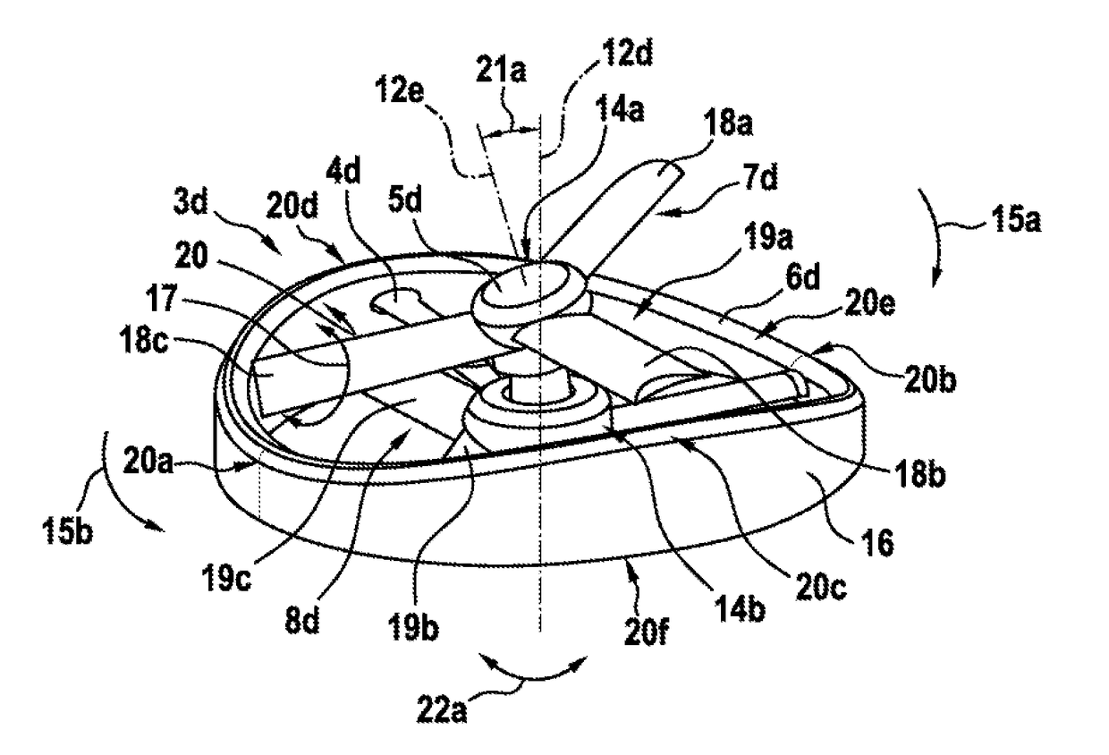
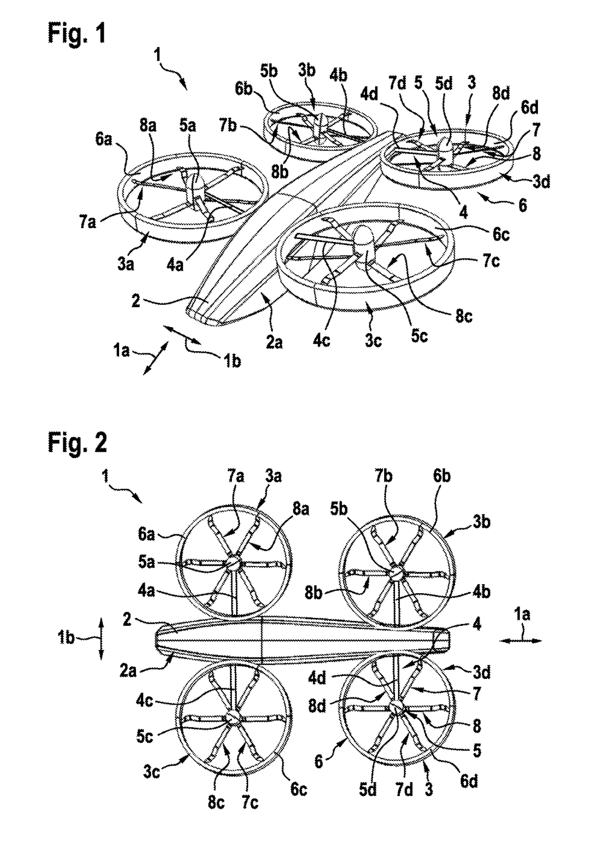
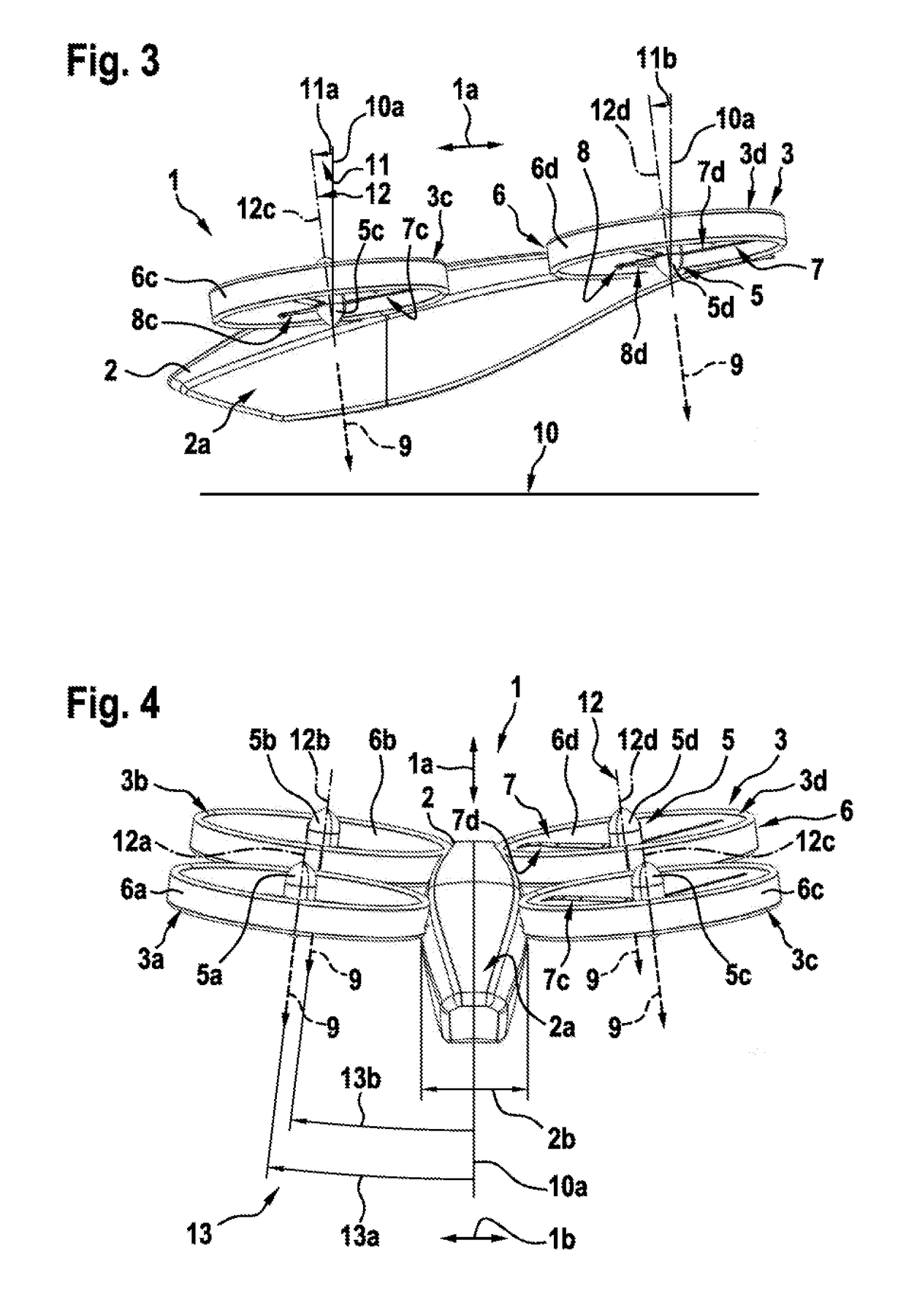
[0070]FIG. 1 shows a multirotor aircraft 1 with an aircraft airframe 2 according to the present invention. The aircraft airframe 2 defines a supporting structure that is also referred to hereinafter as the fuselage of the multirotor aircraft 1.

[0071]The fuselage 2 has an extension in longitudinal direction 1a and an extension in lateral direction 1b and preferably defines an internal volume 2a that is at least adapted for transportation of passengers, so that the multirotor aircraft 1 as a whole is adapted for transportation of passengers. The internal volume 2a is preferably further adapted for accommodating operational and electrical equipment, such as e. g. an energy storage system that is required for operation of the multirotor aircraft 1.

[0072]It should be noted that exemplary configurations of the internal volume 2a that are suitable for transportation of passengers, but also for accommodation of operational and electrical equipment, are readily available to the person skille...


PUM


Abstract

A thrust producing unit for producing thrust in a predetermined direction, comprising at least two rotor assemblies and a shrouding that accommodates at most one of the at least two rotor assemblies, wherein the shrouding defines a cylindrical air duct that is axially delimited by an air inlet region and an air outlet region, and wherein the air inlet region exhibits in circumferential direction of the cylindrical air duct an undulated geometry.

Description

CROSS-REFERENCE TO RELATED APPLICATIONS[0001]This application claims priority to European patent application No. EP 17400008.3 filed on Feb. 27, 2017, the disclosure of which is incorporated in its entirety by reference herein.BACKGROUND OF THE INVENTION(1) Field of the Invention[0002]The invention is related to a thrust producing unit for producing thrust in a predetermined direction, the thrust producing unit comprising at least two rotor assemblies and a shrouding. The invention is further related to a multirotor aircraft with at least one thrust producing unit for producing thrust in a predetermined direction, the thrust producing unit comprising at least two rotor assemblies and a shrouding.2) Description of Related Art[0003]Various conventional multirotor aircrafts are known, e. g. from the documents EP 2 551 190 A1, EP 2 551 193 A1, EP 2 551 198 A1, EP 2 234 883 A1, WO 2015 / 028627 A1, US D678 169 S, U.S. Pat. No. 6,568,630 B2, U.S. Pat. No 8,393,564 B2, U.S. Pat. No. 7,857,25...

Claims


Application Information

Patent Timeline
Patent Type & Authority Applications(United States)
IPC IPC(8): B64C11/00B64C27/08B64C11/48B64C9/14
CPCB64C11/001B64C27/08B64C11/48B64C9/14B64C27/20B64C39/024B64D2241/00B64U10/13B64U30/20B64U50/14B64U50/13B64C29/0016
Inventor KIESEWETTER, UWEMORES, SEBASTIANBEBESEL, MARIUSPFALLER, RUPERT
Owner AIRBUS HELICOPTERS DEUT GMBH
Why Eureka
Try Eureka