Fire-blast resistant door assembly and methods for installing the same

a technology for door assemblies and fire-blast resistant materials, which is applied in the direction of war-like protection, construction, building components, etc., can solve the problems of imposing strict constraints, labor- and time-consuming, and the structure of the door cannot withstand the effecting factors, so as to enhance the fire and blast resistance properties, and not require excessive time and labor costs.

Active Publication Date: 2018-08-30
MIRZEABASOV TIMUR AKHMEDBEKOVICH +1
View PDF15 Cites 4 Cited by
  • Summary
  • Abstract
  • Description
  • Claims
  • Application Information

AI Technical Summary

Benefits of technology

[0035]The methods for installing the door assembly in the door openings according to the present invention allow to enhance the fire and blast resistance properties of the door by using the specifically developed features of the fastening systems that do not comprise the point bolted connections with a bolt arranged transversally to the direction of the air blast exerted on the door. The blast pressure on thus installed door assembly causes only longitudinal collapsing or shearing stresses in welded connections. The strength margin in such welded connections is much higher than the strength of the point connections against the transverse shearing action.
[0036]Concurrently, thanks to the present invention it is possible to install the door assembly essentially in any door opening, in particular, in relatively small and unequipped door openings, where the installation of traditional blast resistant doors is impossible. The latter advantage is provided by creating a mounting contour for the door frame, made by the support frame, with the dimensions exceeding the door frame dimensions. The possibility of creating this specific support frame essentially removes all requirements for equipping the door opening for installing the fire-blast resistant doors.
[0037]Thus, the methods for installing the fire-blast resistant door assembly according to the present invention enhance the fire and blast resistance properties of this assembly, do not require excessive time and labor costs and do not impose strict constraints on the opening for installing the assembly.
[0038]Moreover, it is apparent that, in terms of the usage, the fire-blast resistant door assembly according to the present invention is similar to the traditional door, it does not require exerting considerable efforts to open and close the door for personnel passage and, therefore, it ensures high discharge rate of the door.
[0039]Therefore, the set of features of the present invention in each of its embodiments, described above and specified in the claims of the invention, allows the mentioned technical result to be achieved.

Problems solved by technology

However, the structure of said door is not able to withstand the effecting factors of the explosion, i.e. it is not blast-resistant.
However, the known method used herein for installing the door assembly in the opening before casting or laying the walls is labor- and time-consuming and imposes strict constraints on the opening and the room where said assembly is to be installed, as a whole.
Moreover, the drawbacks of this technical solution are low discharge rate and need for exerting considerable efforts to open the door equipped with the mechanism of handwheel locking.
When the known structure is affected by the explosive blast, the developed excessive pressure, in bolted connections anchoring the mounting brackets or plates to the wall with the opening, causes shearing and collapsing transverse stresses critical for such point anchorages.
This leads to essential decreasing of blast resistance of the structure installed in the opening.
Moreover, this known structure is designed for protecting against the blast effects, the major one being the excessive pressure of the air blast, but not for protecting against the effects of fire, the major one being the thermal radiation.

Method used


Image

  • Fire-blast resistant door assembly and methods for installing the same
  • Fire-blast resistant door assembly and methods for installing the same
  • Fire-blast resistant door assembly and methods for installing the same

Examples


Embodiment Construction

[0044]Hereafter, with reference to the accompanying drawings described is a fire-blast resistant door assembly, as well as methods for installing the same according to the preferred embodiments of the present invention.

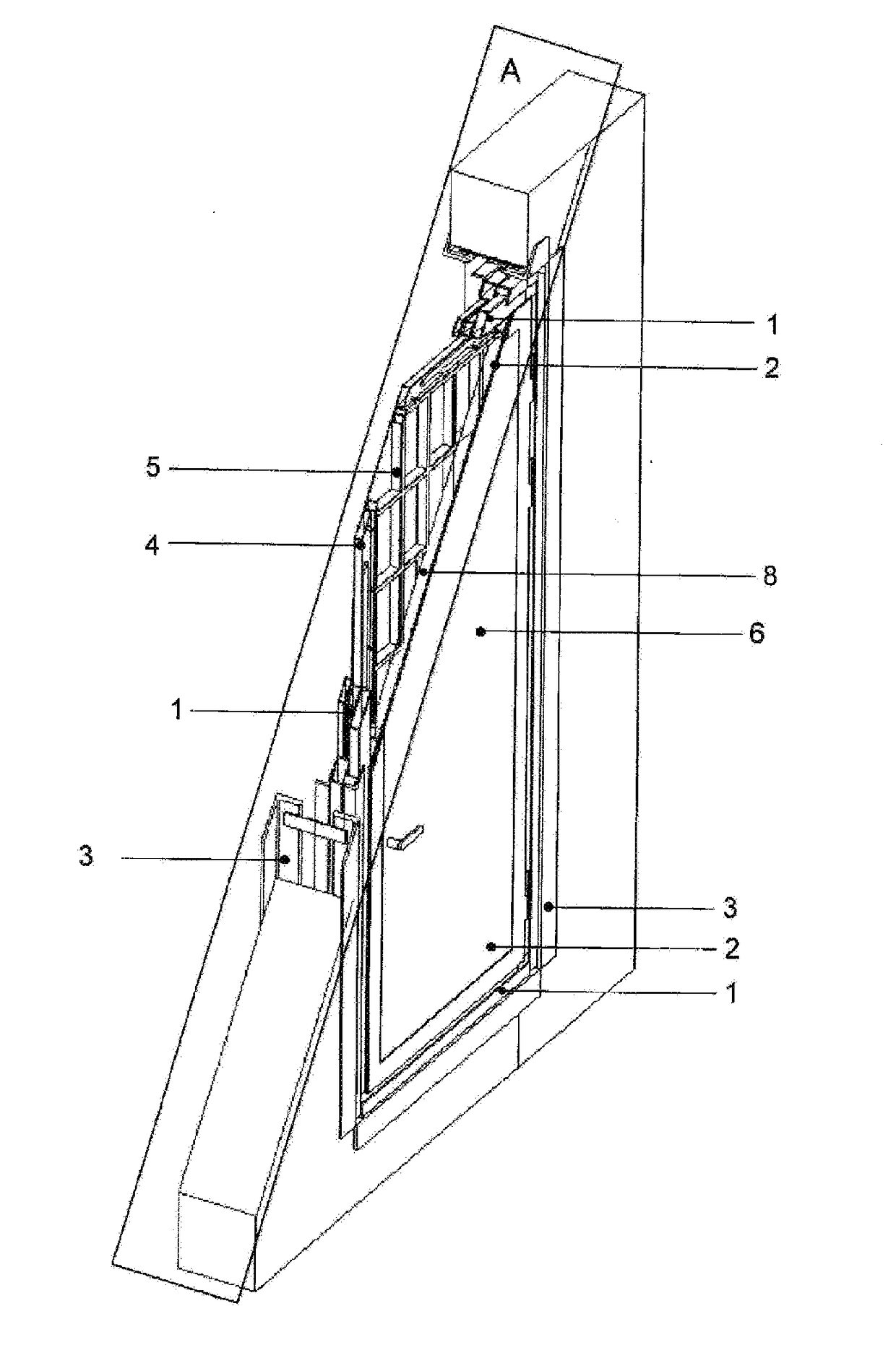
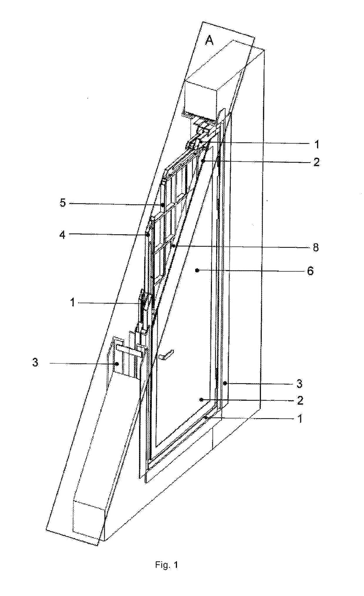
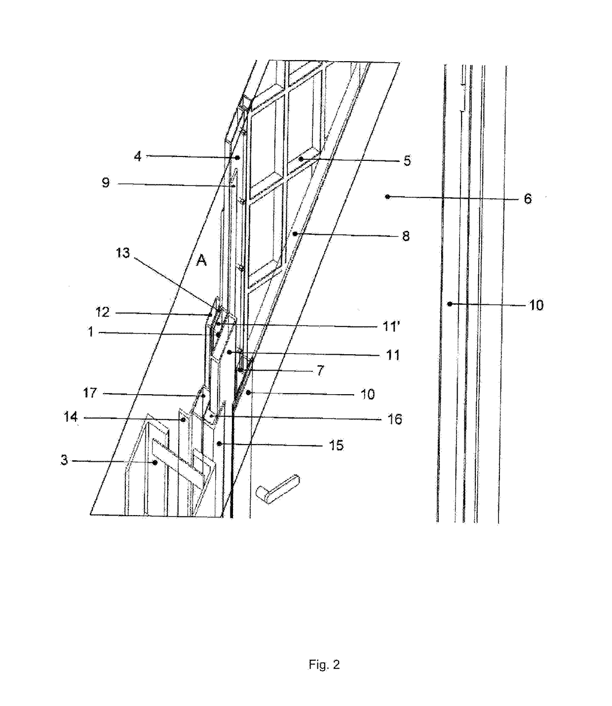
[0045]FIG. 1 schematically illustrates the section with the set of planes parallel to the plane A, of the fire-blast resistant assembly comprising a door frame (1) and a door leaf (2), which is installed in a door opening with a metallic casing (3). FIG. 2 shows the enlarged detail of the fire-blast resistant door assembly. The door leaf (2) is a structure consisting of a rear part and a front part. The rear part of the door leaf (2) comprises a metallic rear panel (20, see FIG. 3), wherein a rear stiffener (4) is welded along the perimeter of this panel, said stiffener being made of hollow pipe sections with rectangular cross-section and forming a closed loop that delimits a mounting cavity. In this cavity, hereinafter referred to as the second mounting cavity, a sup...


PUM


Abstract

A fire-blast resistant door assembly comprises a door frame and a door leaf. The front part of the door leaf comprises a front panel and a front stiffener that delimits a cavity from the inside of the front panel, wherein a sheet refractory material is installed in said cavity. The rear part of the door leaf comprises a rear panel and a rear stiffener that delimits a cavity from the inside of the rear panel. A support structure made of metal is installed in said cavity. The front and the rear parts of the door leaf are mutually connected through the layer of the refractory material, forming the thermal break therebetween, so that said support structure abuts against said sheet refractory material. The door frame, in its turn, comprises a front part and a rear part mutually connected through a layer of the refractory material forming a thermal break.

Description

FIELD OF THE INVENTION[0001]The present invention relates to fire-blast resistant assemblies and, in particular, to a fire-blast resistant door assembly for protecting door openings in industrial and specialized facilities against the effects of air blast and open fire, as well as to methods for installing said fire-blast resistant assembly in door openings.DESCRIPTION OF THE RELATED ART[0002]Known from the prior art is a fire-proof door assembly described in document RU 2488677 C1 (published on Jul. 27, 2013), comprising a door leaf consisting of a metallic framework and an external lining with a material having high thermal resistance and mechanical strength, disposed therebetween. The latter may be, for example, a double-layered aluminosilicate felt, whose layers are separated by a noncombustible reinforced mesh, for instance, from glass fabric or graphite fibers. The entire surfaces of felt, glass fabric and metallic structure are covered with a glue-like mixture of hot-melt glu...

Claims


Application Information

Patent Timeline
Patent Type & Authority Applications(United States)
IPC IPC(8): E06B5/12E06B5/16
CPCE06B5/12E06B5/164E06B5/16E05G1/00
Inventor MIRZEABASOV, TIMUR AKHMEDBEKOVICHBELOV, DMITRIY OLEGOVICH
Owner MIRZEABASOV TIMUR AKHMEDBEKOVICH
Why Eureka
Try Eureka