Cooling system for electronic device

a technology for electronic devices and cooling systems, applied in the direction of cooling/ventilation/heating modifications, instruments, computing, etc., can solve the problems of power consumption, difficult maintenance of electronic devices, and difficulty in completely removing oil attached to electronic devices, so as to achieve efficient removal of heat, improve cooling performance of electronic devices, and reduce maintenance costs

Inactive Publication Date: 2018-08-30
EXASCALER
View PDF6 Cites 37 Cited by
  • Summary
  • Abstract
  • Description
  • Claims
  • Application Information

AI Technical Summary

Benefits of technology

[0029]According to the cooling system of the present invention, the boiling cooling device locally and strongly removes heat from the heat generating component by the vaporization of the first coolant enclosed in the boiling cooling device thermally connected to the heat generating component. At the same time, the second coolant having the boiling point T2 higher than the boiling point T1 of the first coolant completely removes the heat from the boiling cooling device. Thus, the overall electronic device is cooled. In the cooling, the second coolant having a boiling point equal to or higher than the boiling point of the first coolant effectively and strongly cools the peripheral electronic components mounted on the electronic device. That is, the cooling medium for secondary cooling (the second coolant) used for boiling cooling the processor, which is a major heat generating source, also functions as a cooling medium for effective primary cooling of the peripheral electronic components. The first heat exchanger has the high-temperature side passage and the low-temperature side passage alternately provided in separation with a wall, the high-temperature side passage being famed of a group of narrow gaps or a group of micro passages, the high-temperature side passage through which the second coolant is passed, the second coolant having the boiling point T2 (T2=T1 or T2>T1) equal to the boiling point T1 of the first coolant or higher than the boiling point T1 of the first coolant, the low-temperature side passage being formed of a group of narrow gaps or a group of micro passages, the low-temperature side passage through which the third cooling medium is passed, the third cooling medium having the boiling point T3 (T3=T2 or T3<T2) equal to the boiling point T2 of the second coolant or lower than the boiling point T2 of the second coolant. Since the first heat exchanger conducts heat from the second coolant to the third cooling medium, the first heat exchanger efficiently removes heat from the second coolant. In this manner, triple cooling is performed, including the local cooling of the major heat generating source by the boiling cooling device, the overall liquid immersion cooling of the boiling cooling device and the peripheral electronic components, and the heat removal of the cooling medium for secondary cooling by the first heat exchanger. Consequently, cooling performances for the electronic device can be significantly improved. Since a coolant having a relatively high boiling point can be used for the second coolant, the second coolant is less prone to be evaporated, and the cooling bath to contain the second coolant may have an unclosed open space. Thus, this eliminates the necessity of providing a complicated, expensive closing structure. Additionally, the first heat exchanger has the high-temperature side passage formed of a group of narrow gaps or a group of micro passages and the low-temperature side passage formed of a group of narrow gaps or a group of micro passages alternately provided in separation with a wall. The heat exchanger having such a configuration (typically, a plate heat exchanger or a micro channel heat exchanger) has a pressure drop larger than a pressure drop in a typical heat exchanger (e.g. a multitubular heat exchanger including a shell-and-tube heat exchanger), whereas the heat exchanger can obtain high heat transfer performance in a compact size. That is, with the provision of the first heat exchanger in a small size and the pump in a small size configured to pressurize and deliver the cooling medium against a pressure drop in the first heat exchanger, the heat exchange between the third cooling medium and the cooling medium for secondary cooling (the second coolant) enables effective heat removal of the cooling medium for secondary cooling, and the volume occupied by a minimum necessary amount of components is small. Accordingly, the simplification and downsizing of the cooling system are achieved. The first heat exchanger is a small-sized heat exchanger that passes the cooling medium through the passage formed of a group of narrow gaps or a group of micro passages. Thus, a large amount of an expensive cooling medium is unnecessary, and a reduction in cost is enabled.
[0030]Furthermore, in the previously existing boiling cooling system, mechanisms, such as complicated tubes and a large-sized heat sink, are required for cooling the processor that is a major heat generating source. The presence of these mechanisms inevitably interferes with cooling the peripheral electronic components that have to rely on air cooling. Contrary to such previously existing techniques, in accordance with the present invention, complicated tubes and a large-sized heat sink are eliminated, which is advantageous for cooling the peripheral electronic components. Moreover, the cooling medium for secondary cooling (the second coolant) is circulated throughout the overall board of the electronic device. Thus, the peripheral electronic components can be highly efficiently cooled. Note that, in the present specification, the cooling bath with “the open space” also includes cooling baths with a simple closed structure to the extent that the serviceability of the electronic device is not degraded. For example, a structure in which a top plate is detachably or openably mounted on the opening of a cooling bath through a gasket, for example, can be a simple closed structure. Specifically, since the first heat exchanger only has to be a small-sized, lightweight heat exchanger, the first heat exchanger is mechanically holdable on the top plate.
[0031]The object and advantages of the present invention described above and other objects and advantages will be more clearly appreciated through the description of an embodiment below. Of course, the embodiments described below are Examples, which do not limit the present invention.

Problems solved by technology

One of the biggest problems to determine the limits of performances of today's supercomputers is power consumption.
Thus, this causes a difficulty of completely removing the oil attached to an electronic device after the electronic device is taken out of an oil immersion rack.
This leads to a problem in that the maintenance of electronic devices is extremely difficult (specifically, adjustment, inspection, repair, replacement, and extension, for example, and hereinafter, the same meaning is applied).
Moreover, a problem is reported that the synthetic oil for use corrodes a gasket and the other parts configuring the cooling system for a short time to cause leakage, resulting in a hindrance in operation.

Method used


Image

  • Cooling system for electronic device
  • Cooling system for electronic device
  • Cooling system for electronic device

Examples


Embodiment Construction

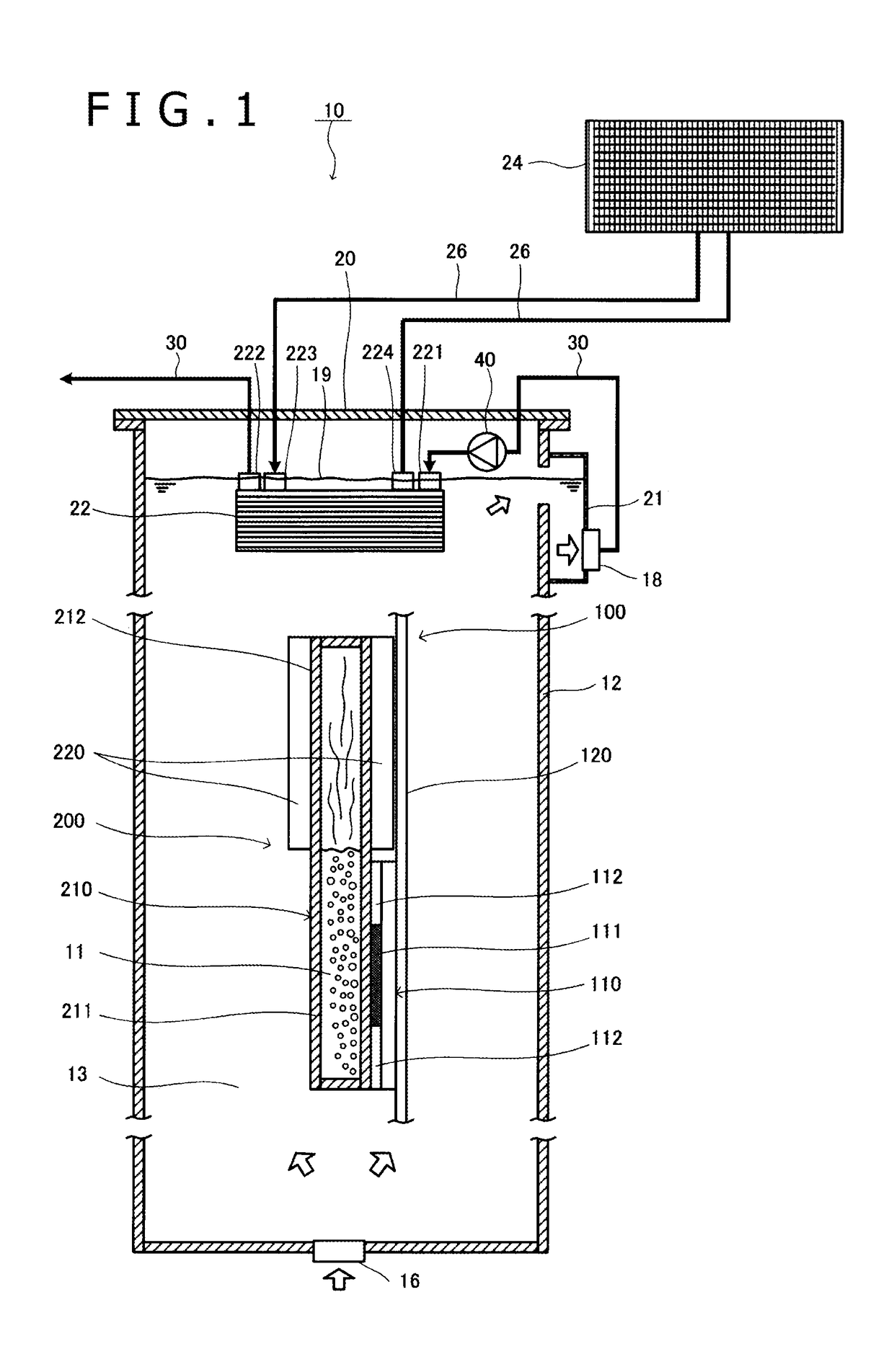
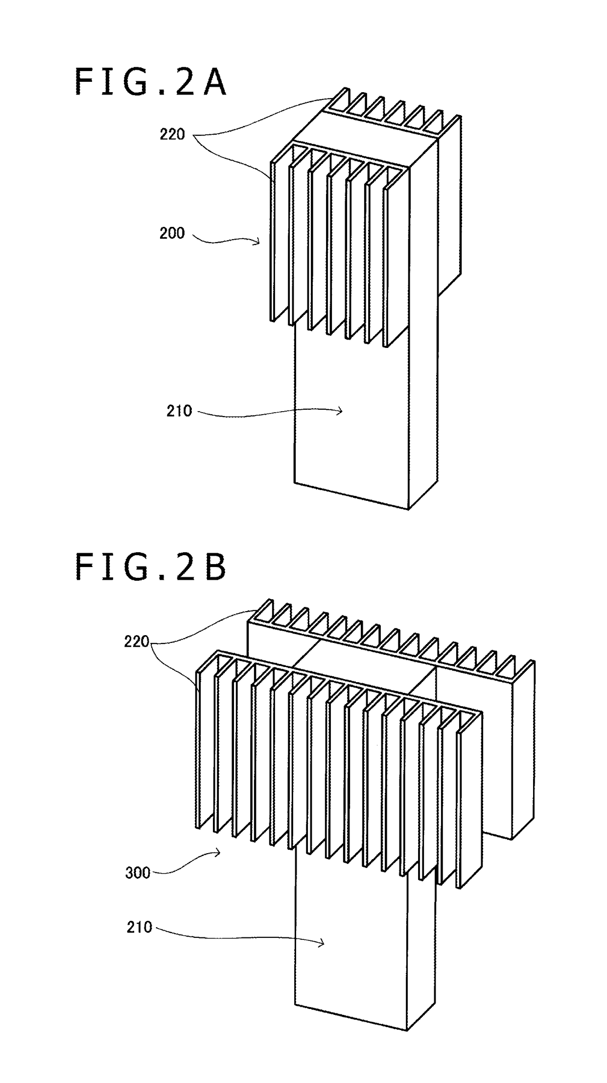
[0043]In the following, preferred embodiments of a cooling system according to the present invention will be described in detail with reference to the drawings. In the description of the embodiments, first, the configuration of the main components of a cooling system according to a preferred embodiment will be described with reference to FIGS. 1, 2A, 2B, and 2C. In the system, an electronic device having a processor, which is a heat generating component, mounted on a board is accommodated in a cooling bath for cooling. The processor includes a die (a semiconductor chip) and a heat spreader surrounding the die. Subsequently, referring to FIGS. 3 and 4, a preferred exemplary configuration of a first heat exchanger will be described. Subsequently, referring to FIG. 5, the overall structure of the cooling system according to a preferred embodiment will be described, while only one unit, as an electronic device, including a board mounted with a plurality of processors is schematically sh...


PUM


Abstract

A cooling system has a cooling bath. The open space of the cooling bath contains a second coolant having a boiling point, and having an electronic device that has a processor that is a heat generating component mounted on a board, and is immersed in the second coolant. A boiling cooling device is thermally connected to the processor, and encloses a first coolant having a boiling point. A first heat exchanger has a high-temperature side passage formed of a group of narrow gaps or a group of micro passages, through which the second coolant is passed, and a low-temperature side passage formed of a group of narrow gaps or a group of micro passages, through which a third cooling medium having a boiling point is passed. A pump is configured to pressurize and deliver the second coolant warmed in the cooling bath toward the inlet of the high-temperature side passage.

Description

TECHNICAL FIELD[0001]The present invention relates to a cooling system for an electronic device, and more specifically to a cooling system for an electronic device, the cooling system efficiently cooling an electronic device that is required to operate in ultra-high performance mode or to operate stably on supercomputers or at data centers, for example, and generates a large quantity of heat.BACKGROUND ART[0002]One of the biggest problems to determine the limits of performances of today's supercomputers is power consumption. The importance of studies on the energy efficiency of supercomputers is already widely recognized. That is, floating point operations per second per watt (FLOPS / Watt) is one indicator to evaluate supercomputers. At data centers, it is estimated that electric power is used for cooling by about 45% of the power consumption in the entire data centers. There is an increasing demand to decrease power consumption by improving cooling efficiency.[0003]Conventionally, a...

Claims


Application Information

Patent Timeline
Patent Type & Authority Applications(United States)
IPC IPC(8): G06F1/20H05K7/20
CPCG06F1/206H05K7/20236H05K7/20254H05K7/20272H05K7/20263H05K7/203H05K7/20327H05K7/20763H05K7/208H05K7/20781H05K7/20818H05K7/20381G06F2200/201G06F1/20H01L23/473H05K7/20
Inventor INABA, KENICHISAITO, MOTOAKI
Owner EXASCALER
Why Eureka
Try Eureka