Diffusing wave spectroscopy apparatus and control method therefor

a wave spectroscopy and apparatus technology, applied in the field of optical imaging, can solve the problems of difficult to accurately apply the probe to the surface of a patient, the probe may not remain stable for long-term measurements, and the rigid flat probe may not accurately conform to the non-flat surface of other anatomies of patients, so as to improve the accuracy of source-detector distance information and improve the dws measurement results.

Inactive Publication Date: 2018-09-06
CANON USA
View PDF14 Cites 14 Cited by
  • Summary
  • Abstract
  • Description
  • Claims
  • Application Information

AI Technical Summary

Benefits of technology

[0009]An object of the present patent application is to improve DWS measurement results by adding a mechanism to measure the distance between the source and detector in the probe to obtain accurate source-detector distance i

Problems solved by technology

In addition, the probes used for DWS measurements are rigid or semi-rigid probes which make it difficult to accurately apply the probe to a patient's surface because of the differences in anatomy and location (e.g., head, leg, arm or finger) of different patients (e.g., neonates vs. adults) do not conform to standardized probes.
Specifically, while rigid flat probes are useful in certain anatomies and locations of certain patients, such rigid flat probes may not accurately conform to non-flat surfaces of other anatomies of patients.
On the other hand, while semi-flexible probes can be forced to conform to the head or other parts of a p

Method used


Image

  • Diffusing wave spectroscopy apparatus and control method therefor
  • Diffusing wave spectroscopy apparatus and control method therefor
  • Diffusing wave spectroscopy apparatus and control method therefor

Examples


first embodiment

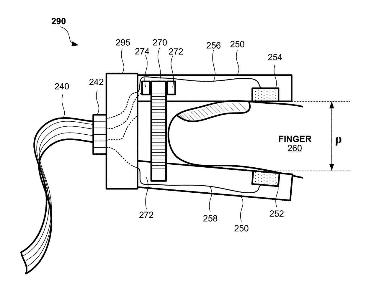
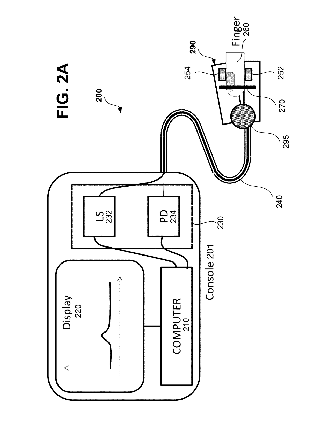
[0037]FIG. 2A illustrates a diffusing wave spectroscopy (DWS) apparatus according to one embodiment of the present patent application. In FIG. 2A, a DWS apparatus 200 includes a DWS probe 290 connected to an operating console 201 via a cable / fiber bundle 240. The operating console 201 is constituted of known DWS controlling parts including a computer 210, a display 220 and a light control module 230. The light control module 230 includes a laser light source (LS) 232 and a photodiode (PD) (photodetector 234) similar to the above-describe light source 32 and photodetector 34 of FIG. 1. The DWS probe 290 is illustrated as a finger clamp composed of a pair of clamp plates joined by a mechanical hinge portion 295 and configured to receive therein a finger 260 (an anatomical extremity). The DWS probe 290 includes a source 252, a detector 254, and an optical encoder 270 which serves to obtain source-detector distance, as described below more in detail.

[0038]FIG. 2B illustrates a configura...

second embodiment

[0069]FIGS. 5A1-5A2 and 5B1-5B2 show examples of a DWS probe having integrated therein one or more linear encoders. FIG. 5A1 shows a probe 500 in the form of a finger clamp (clamping unit) in a closed state in which a linear encoder 502 has been integrated into the probe. FIG. 5A2 shows the probe 500 with a single encoder in an open state. FIG. 5B1 shows a probe 510 also in the form of a finger clamp (clamping unit) in an open state in which a first linear encoder 511 and a second linear encoder 512 have been integrated into the probe. FIG. 5B2 shows the probe 510 with multiple encoders in an open state.

[0070]In FIG. 5A1, the probe 500 includes a pair of clamp plates 504, a hinge portion 508, and a linear encoder 502 with a curved scale 502a. The probe 500 is similar to the above described probe 290 in that probe 500 includes a pair of clamp plates 504 that are mechanically joined by the hinge portion 508. The clamp plates 504 each include a notched section to form a sample receivin...


PUM


Abstract

A DWS apparatus includes a coherent light source, a photodetector, a control unit which can measure an intensity autocorrelation function, a measuring unit which can measure a source-detector distance to obtain source-detector distance data, and a calibrating unit which adjusts the intensity autocorrelation function by using the source-detector distance data. The calibrating unit calibrates the intensity autocorrelation function by adjusting the time constant of the autocorrelation function based on a comparison of the source-detector distance to the time constant of the intensity autocorrelation function.

Description

BACKGROUNDField[0001]The disclosure of this patent application relates generally to optical imaging, and in particular it relates to a diffusing wave spectroscopy apparatus including an encoder that measures source-detector distance, and control methods therefor.Related Art[0002]Diffusing wave spectroscopy (DWS), also known as diffuse correlation spectroscopy (DCS), is a useful technology to detect particle motion in turbid media using coherent light. In DWS, coherent light irradiates a sample (e.g., blood or tissue), the light scattered by the particles in the sample is collected and guided to a detector, and constructive and destructive interference is observed as a random granular pattern of spots (speckle). When scattering particles move in the sample, speckle intensity detected by the detector fluctuates. By counting photon series caused by speckle intensity fluctuation, particle movement in a sample can be estimated precisely. In the case of blood or tissue, the primary moving...

Claims


Application Information

Patent Timeline
IPC IPC(8): A61B5/00G01D5/347G01N21/47
CPCA61B5/0075G01D5/347G01N2201/127G01N2021/4742G01N21/474A61B5/021A61B5/026A61B5/6826G01N21/4785G01N2021/4778G01N2201/121
Inventor HOSODA, MASAKINAKAJI, HARUO
Owner CANON USA
Why Eureka
Try Eureka