
Fuel cell stack and assembly method of same

a fuel cell and stack technology, applied in the direction of fuel cells, electrical equipment, electrochemical generators, etc., can solve the problems of affecting the overall system placement of the corresponding vehicle compartment, affecting the integration of the fuel cell stack, and requiring tight dimensional tolerances of the assembled fuel cell stack,

Active Publication Date: 2018-09-06
HONDA MOTOR CO LTD +1
View PDF0 Cites 0 Cited by
  • Summary
  • Abstract
  • Description
  • Claims
  • Application Information

AI Technical Summary

Benefits of technology

This approach ensures consistent stack dimensions, reduces assembly complexity, minimizes damage, and simplifies environmental sealing, while allowing full access for diagnostic operations and maintaining compressive force during shim insertion or removal.

Problems solved by technology

Integration of fuel cell stacks into automotive platforms is a demanding challenge to the fuel cell system designer, necessitating precise placement and alignment with balance of plant (BOP) equipment that is situated inside of the vehicle's fuel cell system-receiving compartment.
Such integration demands tight dimensional tolerances of the assembled fuel cell stack.
Such variances in stack height make it difficult to design a stack possessive of consistent, repeatable dimensions.
This in turn hampers subsequent BOP connection and overall system placement within the corresponding vehicle compartment.

Method used


Image

  • Fuel cell stack and assembly method of same
  • Fuel cell stack and assembly method of same
  • Fuel cell stack and assembly method of same

Examples


Embodiment Construction

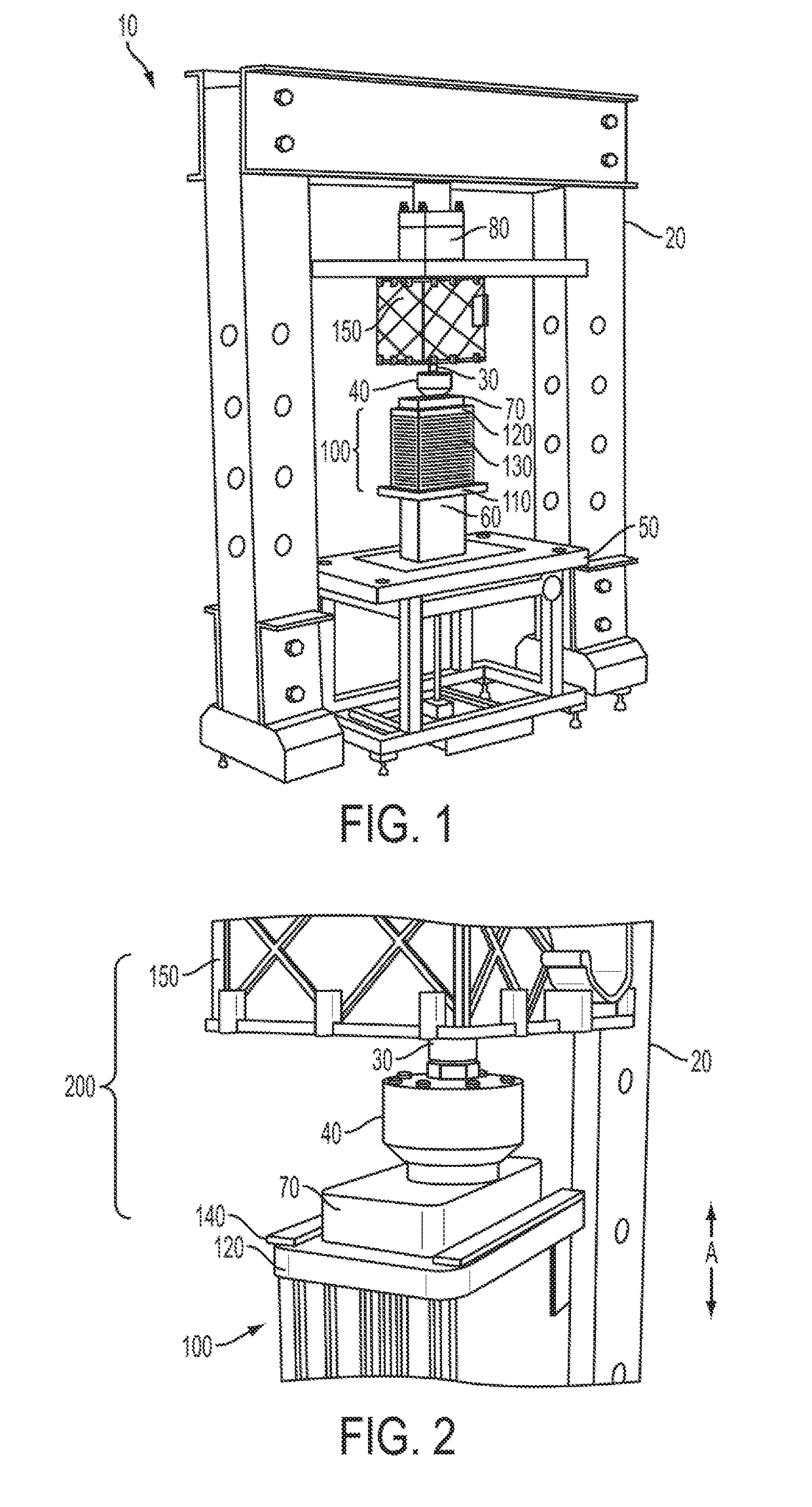
[0020]Referring first to FIGS. 1 and 2, the use of a press 10 to achieve compression of a fuel cell stack 100 is shown. Press 10 includes numerous frame-like members 20, rod 30, load cell 40, assembly platform 50, lower tool 60, upper tool 70 and one or more actuators 80. In the present context, one or more of these press components or portions can be thought of as a pressing agent; the precise nature of such pressing (for example, direct physical contact, response to a larger pressing motion or the like) will be contextually apparent. For example, upper tool 70 may—in conjunction with one form of actuator 80—be made to perform a loading or compressing function that is at least partially independent of a loading or compressing function performed by other moveable press components. By way of example, the movement of tool 70 (as well as the consequent load imparted to stack 100) may be done independently of the press 10 that is responsible for placement and subsequent secured attachme...


PUM

PropertyMeasurementUnit
compressionaaaaaaaaaa
heightaaaaaaaaaa

Abstract

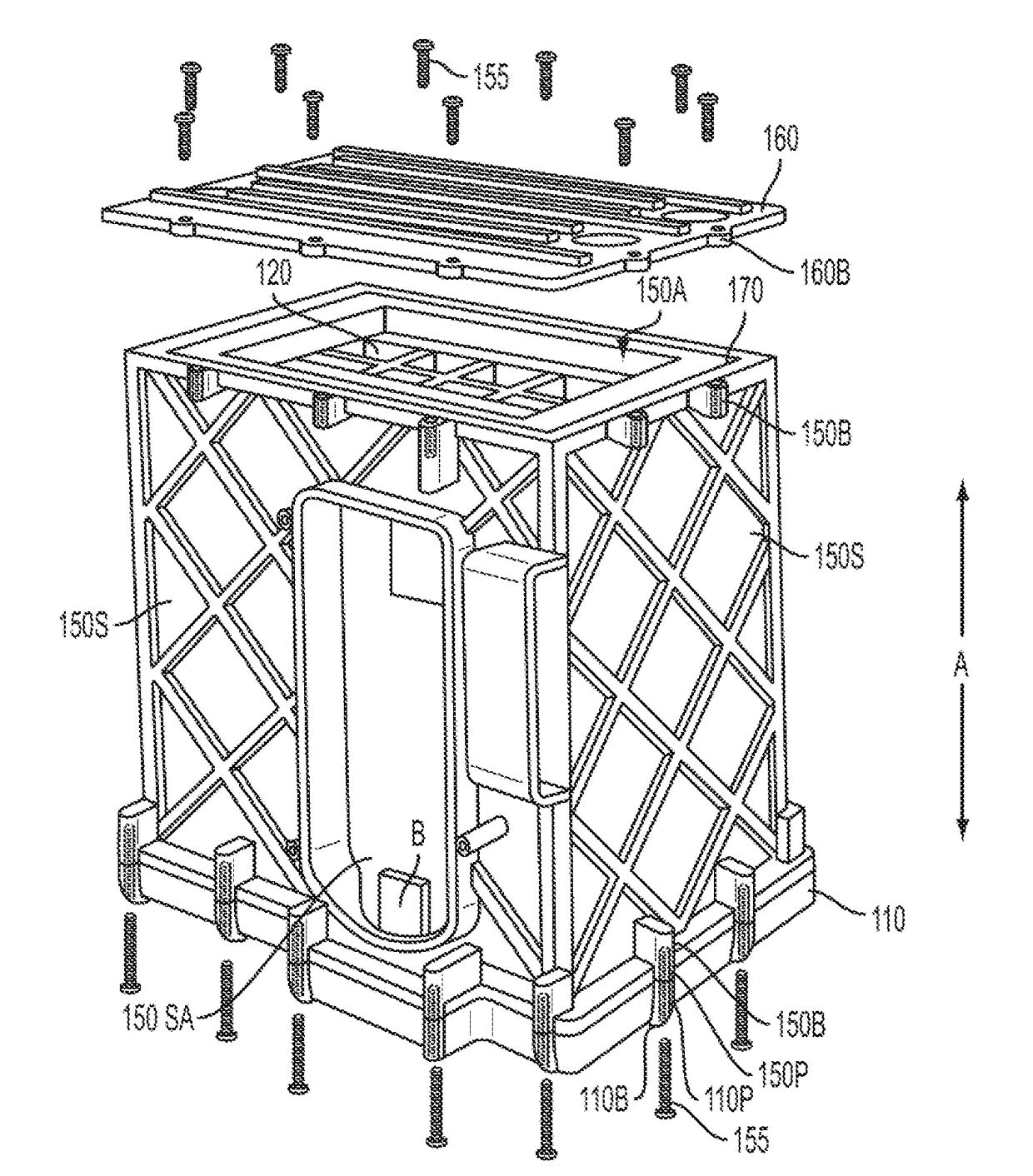
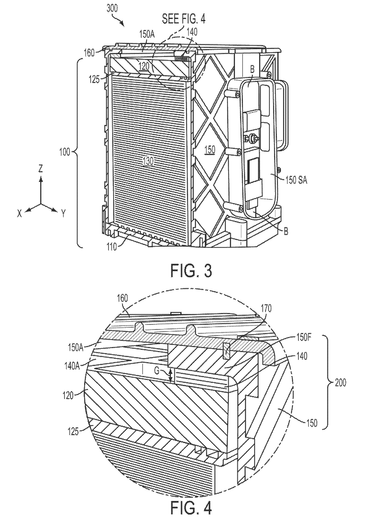
A fuel cell stack and a method of assembling a fuel cell stack includes compressing fuel cells along their stacking axis. A compression retention device made up of an enclosure may be used with one or more optional insertable shims to correct for any stack height variations. Significantly, the enclosure is formed to allow the stack to be loaded in compression by a press such that the cells that make up the stack are placed into and maintained in a substantially compressed state while the compression force is not imparted to the enclosure. By resolving any stack height variances while the cells of the stack are maintained in their substantially compressed state, assembly operations are simplified in that repeated compression and decompression of the stack is avoided while trying to ensure that the stack and enclosure are joined into their final assembly form.

Description

BACKGROUND[0001]The present disclosure relates generally to a fuel cell stack and assembly method thereof, and more particularly to the fuel cell stack and assembly method thereof by the use of an improved compression retention system during fuel cell stack fabrication.[0002]Fuel cells convert a fuel into usable electricity via chemical reaction. A significant benefit to such an energy-producing means is that it is achieved without reliance upon combustion as an intermediate step. As such, fuel cells have several environmental advantages over internal combustion engines (ICEs) and related power-generating sources. In a typical fuel cell—such as a proton exchange membrane or polymer electrolyte membrane (in either event, PEM) fuel cell —a pair of catalyzed electrodes are separated by an ion-transmissive medium (such as Nafion™) The chemical reaction occurs when a gaseous reducing agent (such as hydrogen, H2) is introduced to and ionized at the anode and then made to pass through the ...

Claims


Application Information

Patent Timeline
Patent Type & Authority Applications(United States)
IPC IPC(8): H01M8/2475H01M8/2404H01M8/248
CPCH01M8/2404H01M8/2475H01M8/248H01M8/247H01M8/249Y02E60/50
Inventor MARTINCHEK, DAVID A.THOMPSON, ROBERT CSAKANO, MASAAKITANAKA, HIROYUKI
Owner HONDA MOTOR CO LTD
Learn More