Vehicle body structure

a technology for vehicles and skeletons, applied in the direction of vehicle components, bumpers, superstructure sub-units, etc., can solve the problems of narrow range in which the thickness of the adhesive is adjusted, reduced flexural capacity of the entire vehicle skeleton including the reinforcing material, and reduced flexural capacity of the entire vehicle skeleton. the effect of decreasing the adhesive strength

Active Publication Date: 2018-09-13
TOYOTA JIDOSHA KK
View PDF3 Cites 11 Cited by
  • Summary
  • Abstract
  • Description
  • Claims
  • Application Information

AI Technical Summary

Benefits of technology

[0035]According to the above aspect, the depth of the recessed portion is 5 mm or less. Accordingly, a decline in the adhesive strength of the adhesive attributable to an excessively thick adhesive layer can be suppre...

Problems solved by technology

Accordingly, the range in which the thickness of the adhesive is adjusted becomes narrow, and peeling of the reinforcing material from a vehicle skeleton member may occur at some parts of the vehicle skeleton member beca...

Method used


Image

  • Vehicle body structure
  • Vehicle body structure
  • Vehicle body structure

Examples


first embodiment

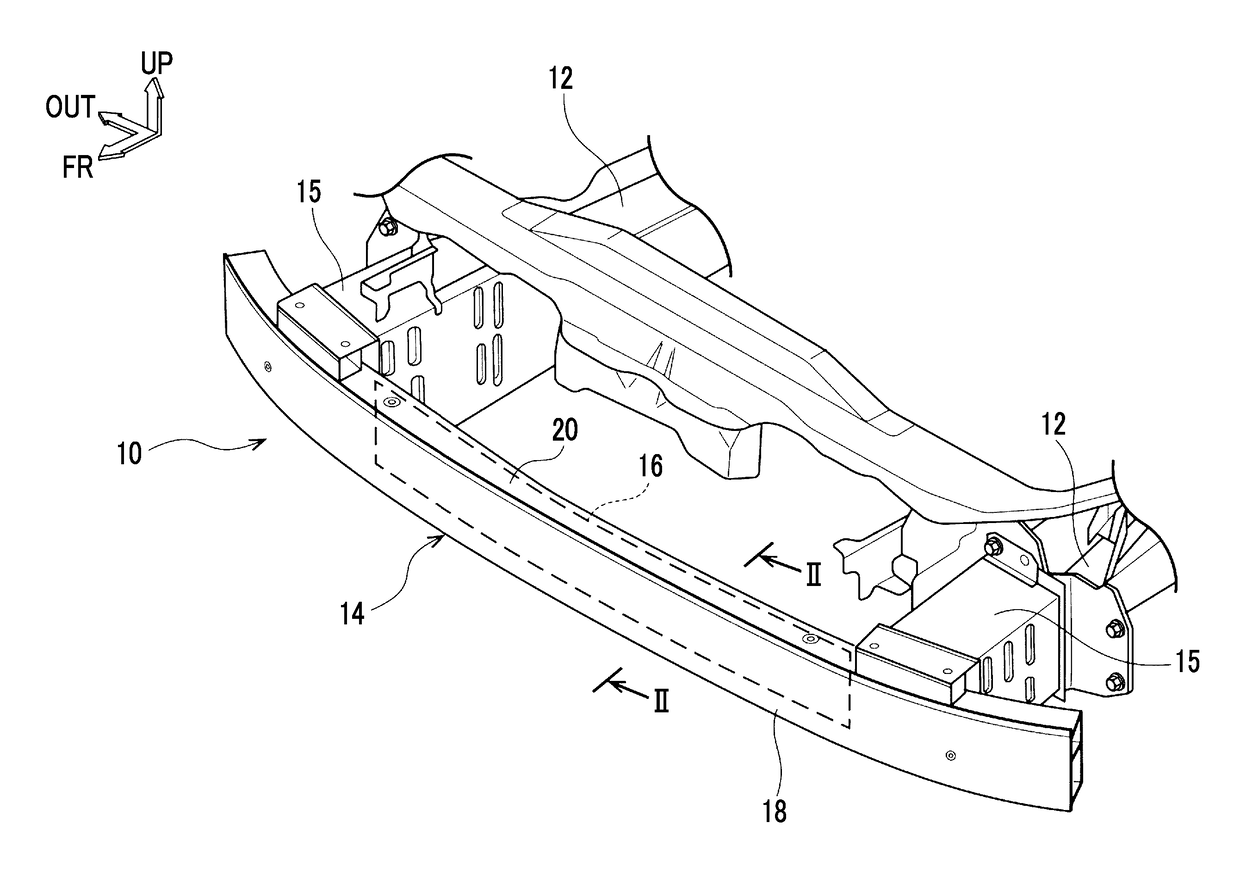
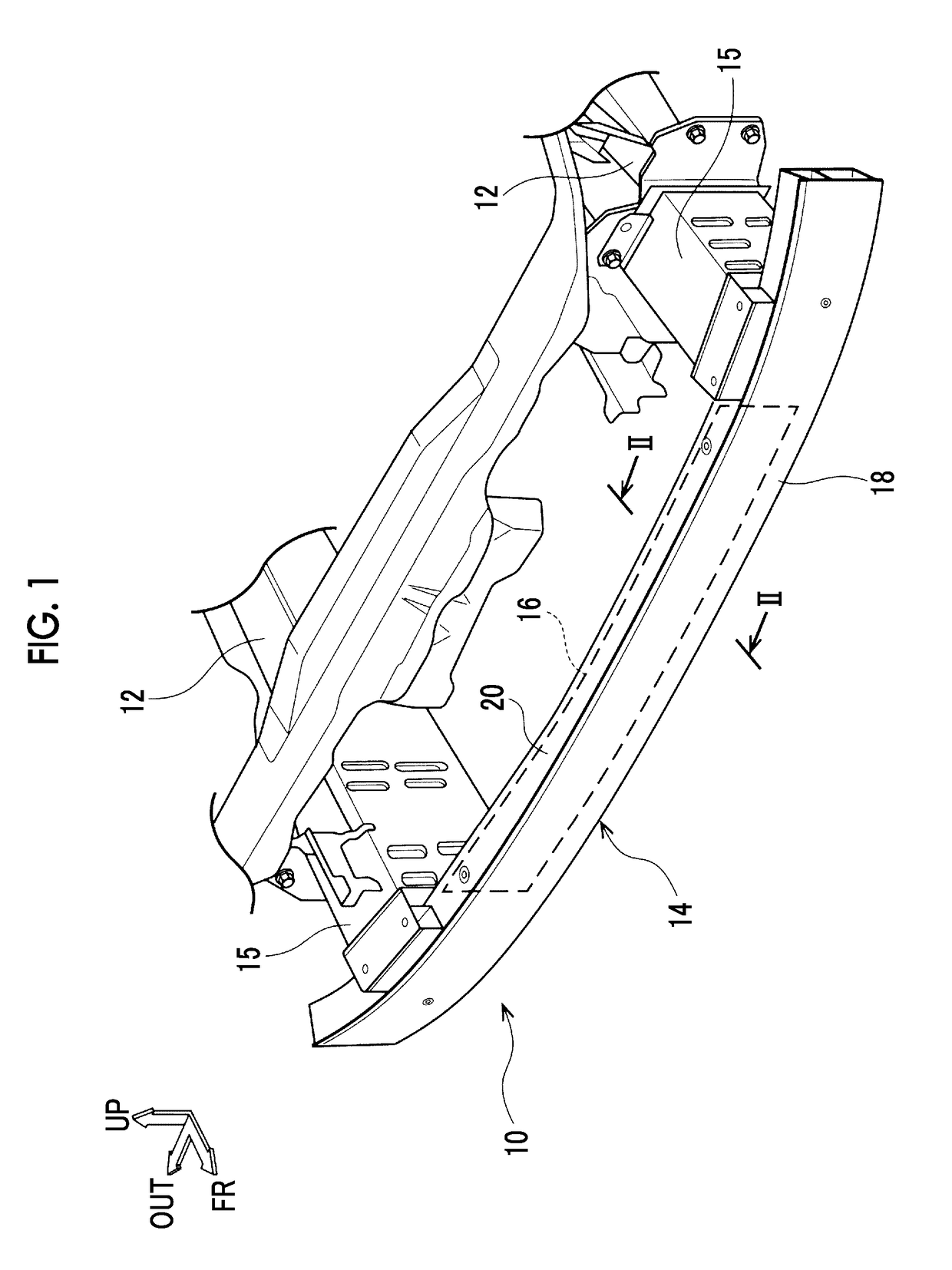
[0048]Hereinafter, a first embodiment of a vehicle body structure according to an aspect of the disclosure will be described with reference to FIGS. 1 to 6. The arrows FR, OUT, and UP that are illustrated in FIGS. 1 to 6 represent the front side of a vehicle in its front-rear direction, the outside in the width direction of the vehicle, and the upper side in the up-down direction of the vehicle, respectively.

[0049]As illustrated in FIG. 1, a front bumper reinforcement (hereinafter, referred to as a “bumper R / F”) 14 as a vehicle skeleton member and a reinforcing material 16 constitute a vehicle body structure 10 disposed in the front portion of the vehicle. The bumper R / F 14 is disposed on the front sides of a pair of front side members 12 in the width direction of the vehicle and is attached to the front side members 12 via crash boxes 15.

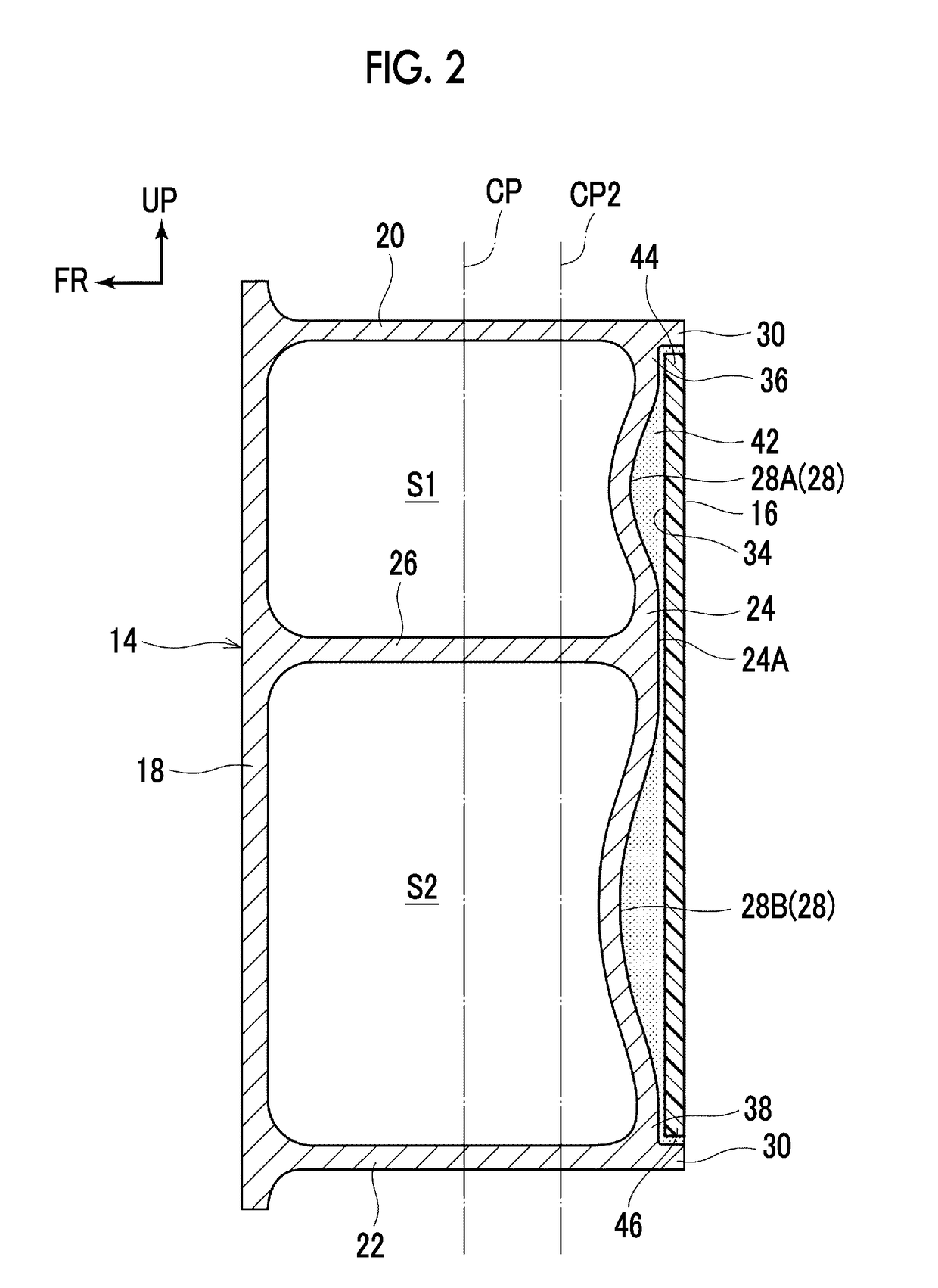
[0050]The bumper R / F 14 is an extruded aluminum alloy material manufactured by extrusion molding or the like, and the bumper R / F 14 according to t...

second embodiment

[0070]Hereinafter, a vehicle body structure according to a second embodiment of the disclosure will be described. The same reference numerals will be used to refer to the components that are basically the same as in the first embodiment, and description thereof will be omitted.

[0071]A vehicle body structure 58 according to the second embodiment has the same basic configuration as the vehicle body structure according to the first embodiment. In the vehicle body structure 58 according to the second embodiment, a plurality of fibers 62 inside a reinforcing material 60 extends in directions intersecting with each other.

[0072]In other words, the reinforcing material 60 is formed by a fiber reinforced resin (CFRP and GFRP) being used and the reinforcing material 60 is formed in a rectangular plate shape extending in the front-rear direction of the vehicle as its thickness direction and in the width direction of the vehicle as its longitudinal direction as illustrated in FIG. 7. In the pre...


PUM


Abstract

A vehicle body structure includes a reinforcing material layer formed of a fiber reinforced resin and a vehicle skeleton member having a closed sectional structure formed of metal. The reinforcing material layer is bonded to a surface of the vehicle skeleton member having a recessed portion recessed toward an inside of the closed sectional structure. An adhesive is disposed at least between the recessed portion and the reinforcing material layer.

Description

INCORPORATION BY REFERENCE[0001]The disclosure of Japanese Patent Application No. 2017-043103 filed on Mar. 7, 2017 including the specification, drawings and abstract is incorporated herein by reference in its entirety.BACKGROUND1. Technical Field[0002]The disclosure relates to a vehicle body structure.2. Description of Related Art[0003]Japanese Unexamined Patent Application Publication No. 2015-160524 (JP 2015-160524 A) discloses a B pillar (center pillar) that constitutes a part of a side door opening portion disposed in a side portion of a vehicle. The B pillar is formed by bonding an inner panel to an outer panel and has a hat shape in section. A carbon fiber reinforced plastic (CFRP)-based reinforcing material that has a sheet shape is bonded to the inner panel in the up-down direction of the vehicle. As a result, the flexural capacity of the entire B pillar including the reinforcing material is improved.SUMMARY[0004]In the case of the configuration that is disclosed in JP 2015...

Claims


Application Information

Patent Timeline
IPC IPC(8): B60R19/03B60R19/18
CPCB60R19/03B60R19/18B60R2019/1813B60R2019/1853B60R2019/182B60J5/0447B60R2019/186B60J5/0484B62D29/005B62D25/04B60R2021/0023B60R2021/0006B60R19/02B62D25/00
Inventor KITAKATA, SHINTARO
Owner TOYOTA JIDOSHA KK
Why Eureka
Try Eureka