Bunker system for radiation therapy equipment

a radiation therapy equipment and bunker technology, applied in the field of bunker systems, can solve the problems of increasing the overall labor cost, unable to achieve the full operability of the radiation therapy room, and the construction of the bunker system in a time-consuming fashion, and achieve the effect of effective shielding the outside environment, reliable, consistent and uniform radiation shielding characteristics

Inactive Publication Date: 2018-09-13
NEW ENGLAND LEAD BURNING CO INC
View PDF18 Cites 12 Cited by
  • Summary
  • Abstract
  • Description
  • Claims
  • Application Information

AI Technical Summary

Benefits of technology

[0011]It is another object of the present invention to provide a bunker system as described above that is configured to completely surround the radiation therapy equipment and effectively shield the outside environment form any radiation generated therefrom.
[0012]It is yet another object of the present invention to provide a bunker system as described above that can be constructed and fully operable within a limited duration of time.
[0013]It is still another object of the present invention to provide a bunker system as described above that readily allows for the installation of any required radiation therapy equipment infrastructure, such as ductwork, wiring and the like, during its construction process.
[0014]It is yet still another object of the present invention to provide a bunker system that maintains reliable, consistent and uniform radiation shielding characteristics.

Problems solved by technology

As a first drawback, bunker systems of the type as described above are constructed in a time-consuming fashion due, largely in part, to the inclusion of cast-in-place concrete walls of considerable thickness.
As a result, full operability of a radiation therapy room is often not achieved until at least one year after initiating construction.
As second drawback, bunker systems of the type as described above are commonly constructed in a largely inefficient fashion, which may cause an increase in overall labor costs.
This inability to enable different workers to engage in the various installation steps in parallel, coupled with the significant cure time associated with the concrete walls, creates significant delays in the overall construction process.
As a third drawback, bunker systems of the type as described above are often constructed without adequate quality control.
In particular, due to the considerable thickness required for each wall, cast-in-place concrete is often deposited through a multi-stepped pouring process that can create notable variances in density within each wall (e.g., due to the inadvertent introduction of air therein or the presence of voids, cold joints, and honeycombs).
As can be appreciated, such variances in concrete density can compromise the shielding performance of certain walls, which is highly undesirable.

Method used


Image

  • Bunker system for radiation therapy equipment
  • Bunker system for radiation therapy equipment
  • Bunker system for radiation therapy equipment

Examples


Embodiment Construction

Bunker System 11

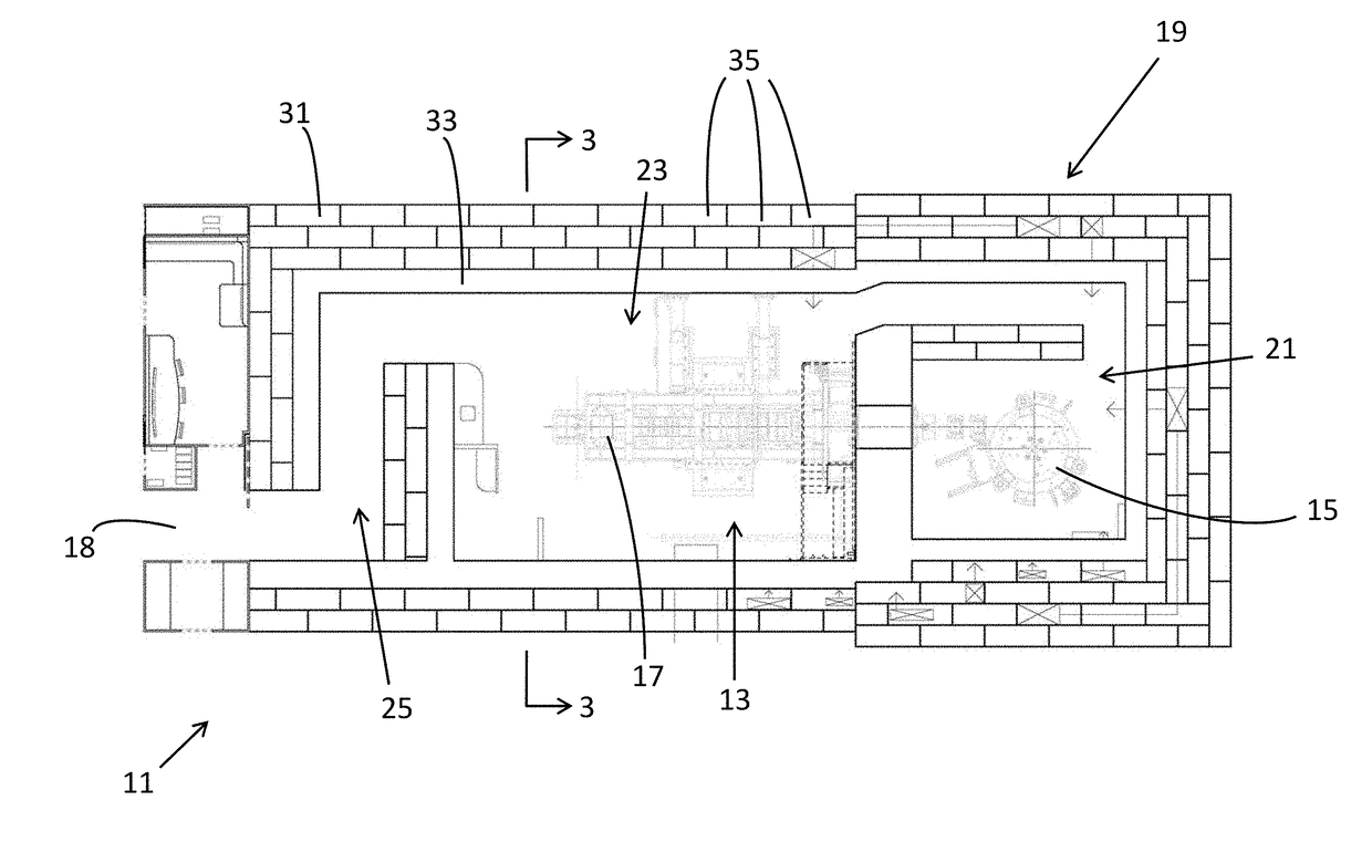
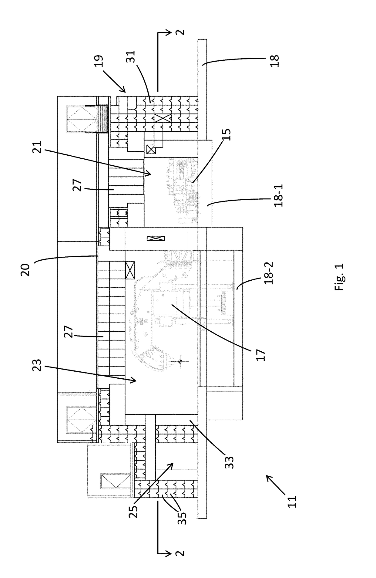
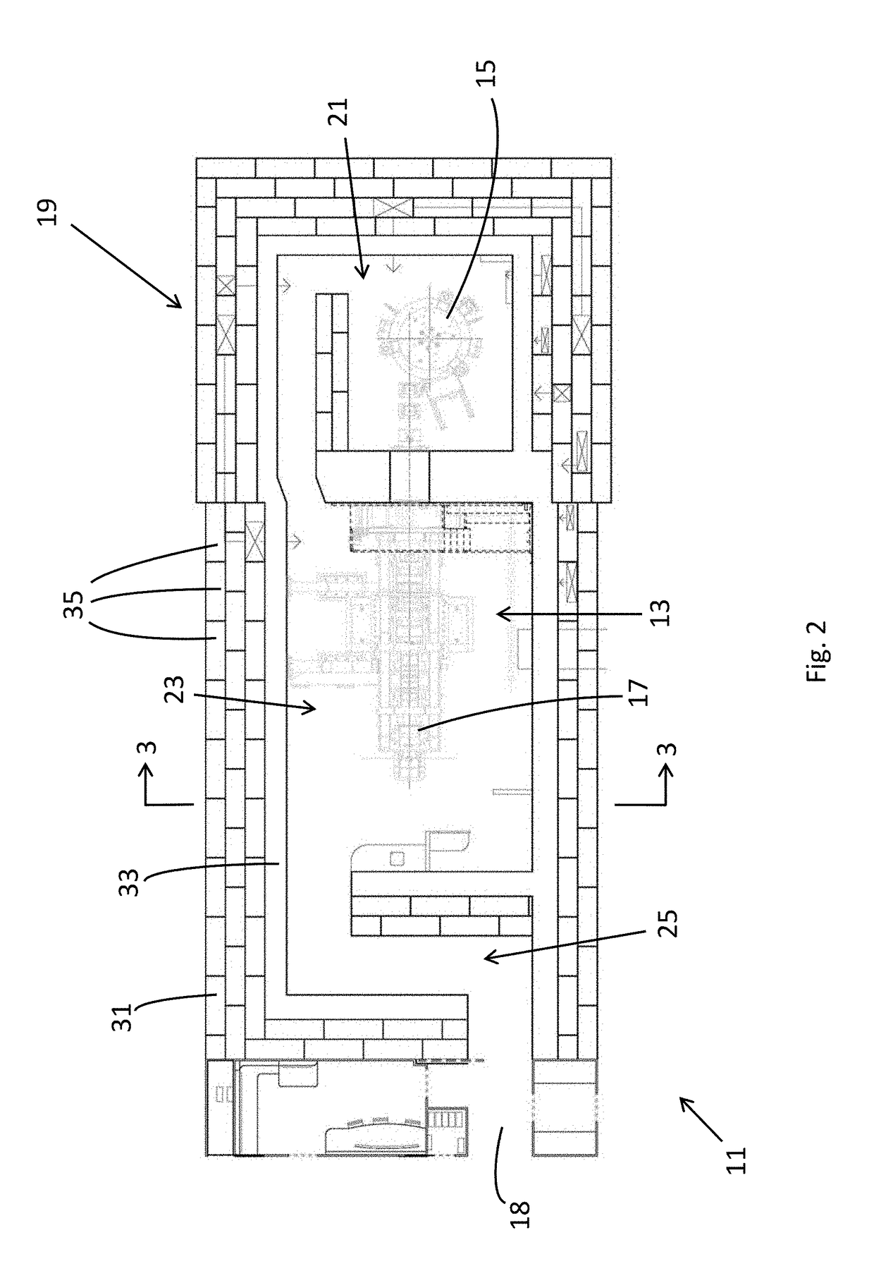
[0024]Referring now to FIGS. 1-3, there is shown a novel bunker system constructed according to the teachings of the present invention, the bunker system being identified generally by reference numeral 11. As will be explained in detail below, bunker system 11 utilizes a multi-core radiation shielding construction which provides several notable advantages including, but not limited to, quick and efficient assembly, enhanced quality control, and reusability.

[0025]In the description that follows, bunker system 11 is explained in the context of providing radiation shielding for a radiation treatment device 13. As defined herein, radiation treatment device 13 represents any instrument in the radiation therapy field that is able to deliver focused, high-energy waves to a patient. Accordingly, it should be understood that the bunker system 11 is not limited for use in connection with any particular type or style of radiation therapy machine. Rather, bunker system 11 could ...


PUM


Abstract

A bunker system for shielding radiation emitted from a radiation treatment device includes a multi-core wall structure that completely surrounds the radiation treatment device. The wall structure includes a cast-in-place concrete inner core of limited thickness in order to minimize curing time requirements. The inner core is immediately surrounded by an outer core constructed from a plurality of preformed modular blocks. Each modular block is constructed of a radiation shielding material, such as concrete. As part of the assembly process, the preformed modular blocks are designed to be stacked top-to-bottom and side-by-side in an interlocking fashion to form a continuous wall structure, with blocks additionally arranged in a front-to-back relationship to achieve the required outer core thickness. The dual-core construction of the wall structure enables the bunker system to be quickly and efficiently assembled with enhanced quality control and potential reusability.

Description

FIELD OF THE INVENTION[0001]The present invention relates generally to radiation therapy equipment and, more particularly, to bunker systems designed to shield radiation generated from such equipment.BACKGROUND OF THE INVENTION[0002]In the medical field, radiation is commonly utilized to treat cancer by emitting focused, high-energy waves onto a patient in order to shrink and / or destroy tumor cells without significantly impinging healthy cells. Radiation is generated and delivered using radiation therapy equipment located at designated treatment facilities, such as hospitals and cancer treatment centers.[0003]To prevent the escape of radiation outside of the designated treatment area, radiation therapy equipment is traditionally located within an enlarged bunker system, or radiation room. Due to its critical importance in effectively shielding radiation, a bunker system is typically engineered by a physicist with expertise in the field as part of the architectural process in designi...

Claims


Application Information

Patent Timeline
Patent Type & Authority Applications(United States)
IPC IPC(8): E04H3/08E04B2/08E04B2/84E04B5/32E04B7/20E02D27/44E04C1/00E06B5/18E04C5/06A61N5/10
CPCE04H3/08E04B2/08E04B2/84E04B5/32E04B7/20E02D27/44E04C1/00E06B5/18E04C5/06A61N5/10E04B2002/021E04B2002/0228E04B2002/0258E04B2103/02A61N2005/1094G21F3/04G21F7/00
Inventor LEBLANC, RICHARD J.MILLER, GARY J.
Owner NEW ENGLAND LEAD BURNING CO INC
Why Eureka
Try Eureka