
Roller bearing and a mechanical system comprising such a roller bearing

a technology of roller bearings and mechanical systems, applied in the direction of bearings, sliding contact bearings, rigid support of bearings, etc., can solve the problems of increasing friction torque, increasing friction torque, and increasing friction torque of roller bearings, etc., to achieve easy manufacturing, easy transportation and assembly

Active Publication Date: 2018-09-13
AB SKF
View PDF6 Cites 0 Cited by
  • Summary
  • Abstract
  • Description
  • Claims
  • Application Information

AI Technical Summary

Benefits of technology

The invention aims to provide an improved roller bearing that is easy to manufacture and assemble, and has increased load capacity. The cage is designed to maintain its position and can be easily mounted on a shaft, reducing friction and power losses. The additional weight of the at least one boss is negligible. Overall, this design allows for a simplified assembly process and a more robust arrangement.

Problems solved by technology

It induces shocks and vibrations of cage, and increase friction torque between cage and thrust collar and should of the shaft.
However, the tolerances are very strict but contact may still occur between the cage and the abutting surfaces, increasing the friction torque of roller bearing.

Method used


Image

  • Roller bearing and a mechanical system comprising such a roller bearing
  • Roller bearing and a mechanical system comprising such a roller bearing
  • Roller bearing and a mechanical system comprising such a roller bearing

Examples


Embodiment Construction

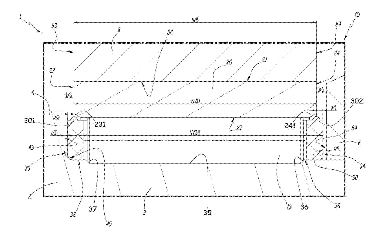
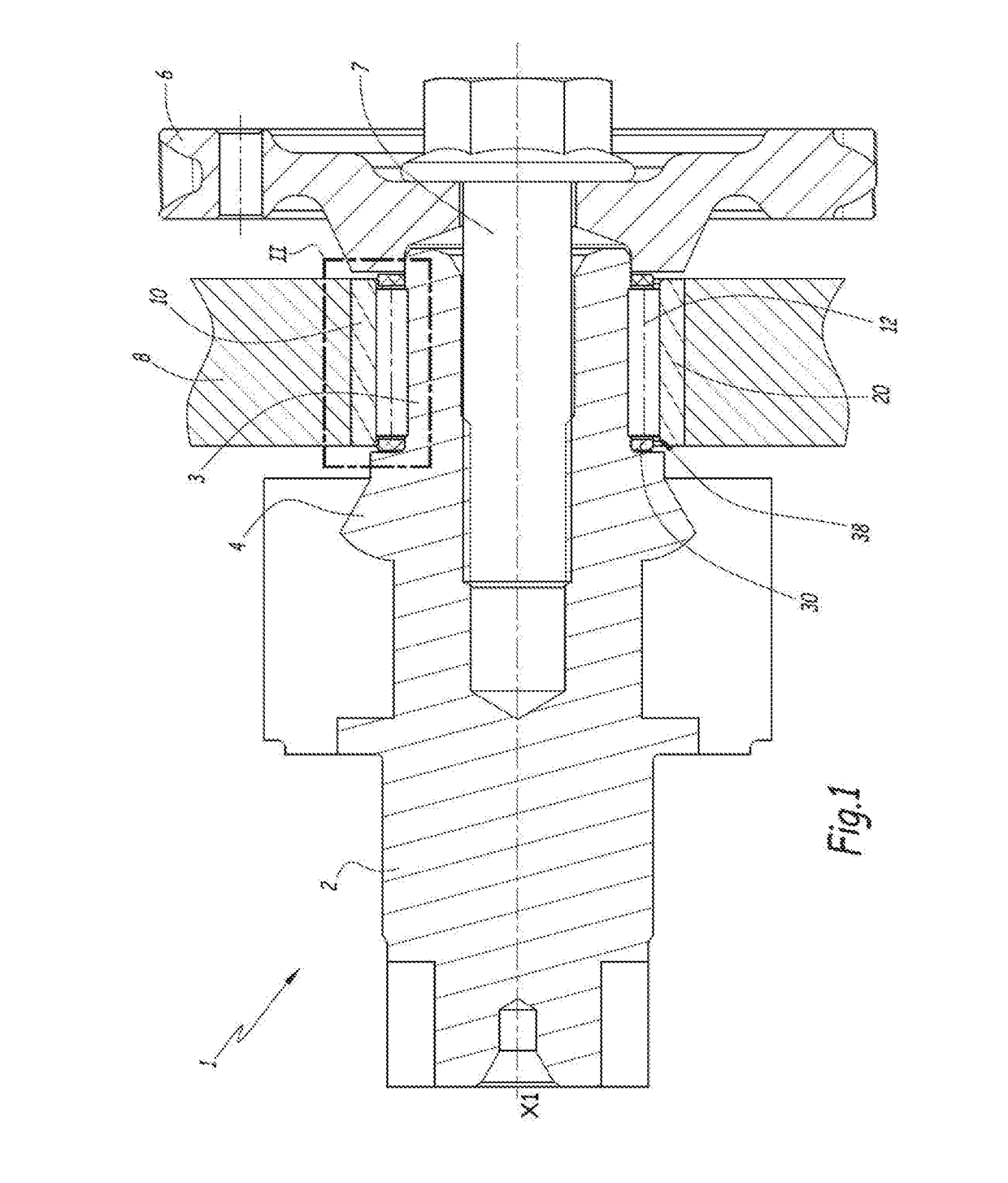
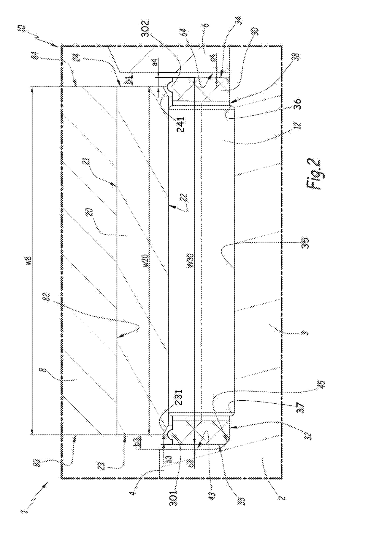
[0037]FIGS. 1 and 2 partly show a mechanical system 1 according to the invention, for example a vehicle engine.

[0038]System 1 comprises a balancing shaft 2 including an axial part 3 and a radial part 4, a gear 6 secured to the shaft 2 by a screw 7, and a housing 8 axially located between radial part 4 and gear 6. In the present case, radial part 4 is a counterweight or unbalanced mass. A lateral surface 43 or radial part 4 and a lateral surface 64 of gear 6 are axially facing each other. Housing 8 comprises a cylindrical inner bore 82 and two lateral surfaces 83 and 84 defining a housing width w8.

[0039]Moreover, system 1 comprises a roller bearing 10 also defined according to the invention. Roller bearing 10 is mounted radially on axial part 3 of shaft 2 and in bore 82 of housing 8, and axially between surface 43 of radial part 4 and surface 64 of gear 6. Roller bearing 10 is centered on a central axis X10 and comprises rollers 12, an outer ring 20 and a cage 30. Rollers 12 are need...


PUM


Abstract

A roller bearing configured to be mounted on a balancing shaft. The rolling bearing having an outer ring, a cage axially protruding beyond at least one side of the outer ring, and rollers mounted in the cage and in rolling contact with the outer ring. The cage provides at least one boss on a side that axially protrudes beyond the outer ring, the boss being dedicated to come into abutment against the outer ring in case of relative axial displacement between the cage and outer ring.

Description

CROSS-REFERENCE[0001]This application claims priority to German patent application no. 102017203698.2 filed on Mar. 7, 2017, the contents of which are fully incorporated herein by reference.TECHNOLOGICAL FIELD[0002]The present invention concerns a roller bearing, adapted for mounting on a balancing shaft. The invention also concerns a mechanical system, for example a vehicle engine, comprising a balancing shaft and such a roller bearing.BACKGROUND[0003]U.S. Pat. No. 3,384,429 discloses an example of needle roller bearing, comprising an outer ring, a cage and needles mounted in pockets of the cage. The roller bearing also comprises thrust rings detachably secured on both sides of the outer ring. The roller bearing is mounted on a shaft, with the thrust rings disposed in bearing contact against a thrust collar and a shoulder of the shaft.[0004]In practice, a relative axial displacement may occur between the cage and the outer ring and the shaft. It induces shocks and vibrations of cag...

Claims


Application Information

Patent Timeline
IPC IPC(8): F16C19/46F16C21/00F16C19/36F16C17/04
CPCF16C21/005F16C19/364F16C17/04F16C19/466F16C19/44F16C33/46F16C35/06F16C19/463F16C33/4605F16C33/586
Inventor MAFFUCCI, JULIENHAMAR, VINCENTMETZ, HARALD
Owner AB SKF
Learn More