Vehicle heat management device

a technology for heat management devices and vehicles, applied in the direction of defrosting, domestic cooling devices, applications, etc., can solve the problems of poor energy utilization efficiency and the use of engine motive power, and achieve the effect of suppressing the drop in energy utilization efficiency

Active Publication Date: 2018-09-13
TOYOTA JIDOSHA KK
View PDF4 Cites 12 Cited by
  • Summary
  • Abstract
  • Description
  • Claims
  • Application Information

AI Technical Summary

Benefits of technology

[0005]An object of the present disclosure is to suppress a drop in the

Problems solved by technology

However, although the engine is originally intended for use as a heat engine in which energy obtained by burning fuel is converted into motive power, the technology of JP-A No. 2008-221997 does not utilize the motive power obta

Method used


Image

  • Vehicle heat management device
  • Vehicle heat management device
  • Vehicle heat management device

Examples


first exemplary embodiment

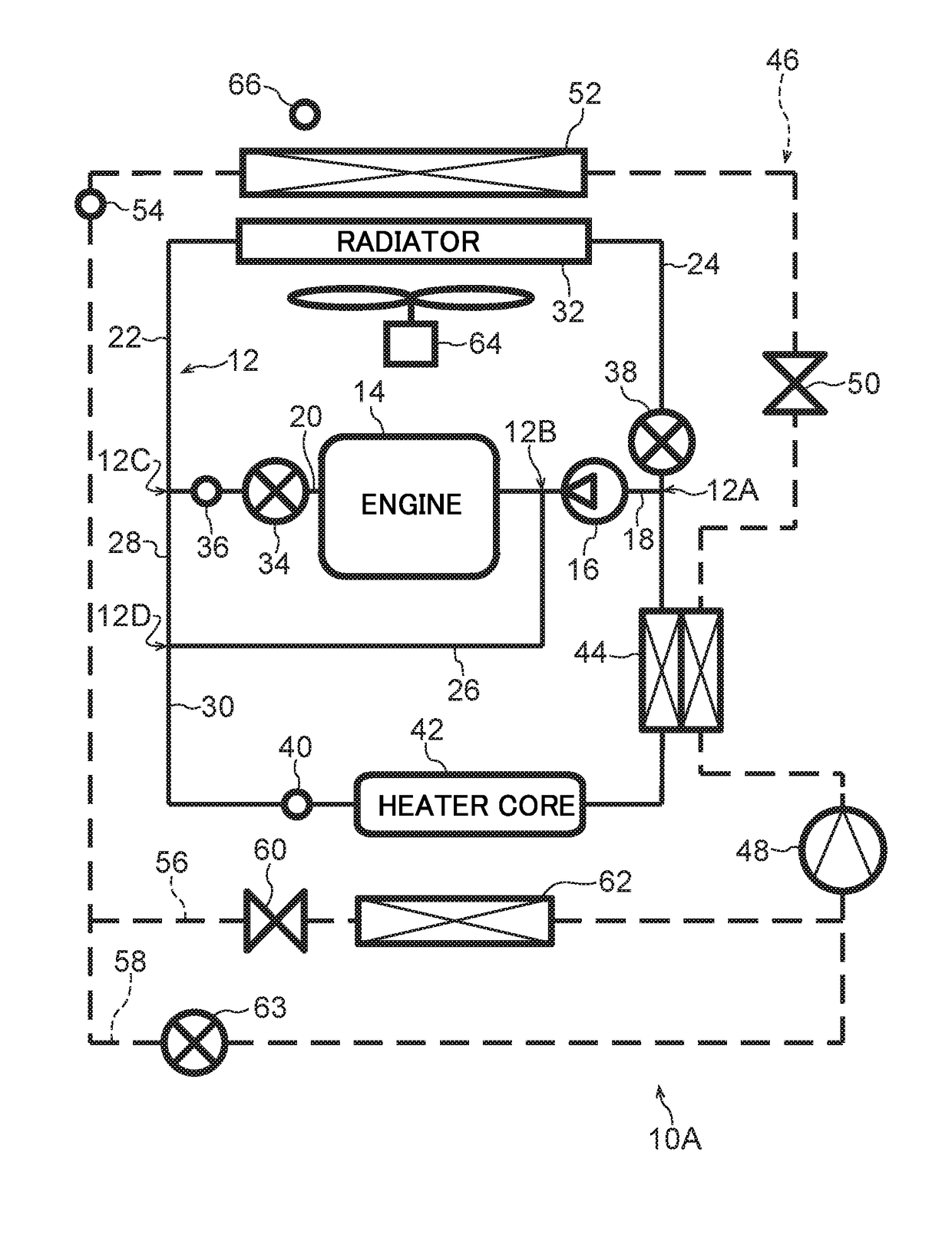
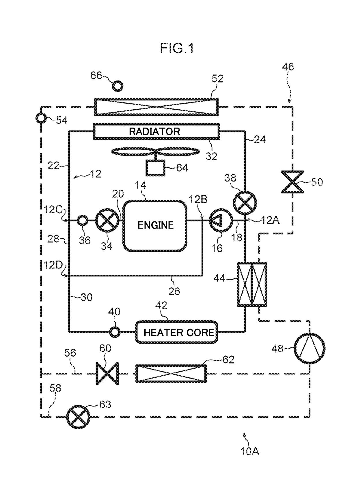
[0025]FIG. 1 illustrates a vehicle heat management system 10A according to a first exemplary embodiment. The vehicle heat management system 10A includes a cooling device that cools an engine 14, this being an example of a heat generating body of a vehicle, by circulating cooling water around a cooling water circulation path 12, and an air-conditioning device that air-conditions the interior of a vehicle cabin of the vehicle by circulating a heat exchange medium around a heat exchange medium circulation path 46. Note that in FIG. 1, the cooling water circulation path 12 is illustrated by solid lines, and the heat exchange medium circulation path 46 is illustrated by dashed lines.

[0026]The cooling water circulation path 12 is provided with a water pump (referred to below as “WP”) 16, this being an example of a pump to circulate the cooling water around the cooling water circulation path 12 to cool the engine 14. The WP 16 may be a mechanical WP actuated using the engine 14 as a drive ...

second exemplary embodiment

[0082]Next, explanation follows regarding a second exemplary embodiment of the present invention. Note that portions equivalent to those of the first exemplary embodiment are allocated the same reference numerals and explanation thereof is omitted, with explanation only being given regarding points that differ.

[0083]As illustrated in FIG. 6, a vehicle heat management system 10B according to the second exemplary embodiment differs from the vehicle heat management system 10A (FIG. 1) described in the first exemplary embodiment in the point that a third solenoid valve 100 is provided partway along the pipe 30. The third solenoid valve 100 can be opened and closed, and is provided between the connection point 12D and the second water temperature sensor 40. When the third solenoid valve 100 is in an open state, cooling water flows through the inside of the pipe 30, and when the third solenoid valve 100 is in a closed state, the flow of cooling water through the pipe 30 is stopped. The th...

third exemplary embodiment

[0089]Next, explanation follows regarding a third exemplary embodiment of the present invention. Note that elements equivalent to those of the first exemplary embodiment and the second exemplary embodiment are allocated the same reference numerals and explanation thereof is omitted, with explanation being given only regarding points that differ.

[0090]As illustrated in FIG. 10, a vehicle heat management system 10C according to the third exemplary embodiment differs from the vehicle heat management system 10B (FIG. 6) described in the second exemplary embodiment in the point that the pipes 26, 28 connecting the connection point 12B and the connection point 12D together are omitted. An end of the pipe 30 is thus connected to ends of the pipes 20, 22 at the connection point 12C.

[0091]Note that similarly to in the vehicle heat management system 10C, the pipes 26, 28 may also be omitted from the vehicle heat management system 10A (FIG. 1) described in the first exemplary embodiment or the...


PUM


Abstract

A vehicle heat management device that includes: a pump that circulates cooling water around a cooling water circulation path; an air blower that blows air through a radiator toward an exterior heat exchanger of an air-conditioning device of a vehicle; and a de-icing controller that, in a case in which an estimated ice adhesion amount on the exterior heat exchanger is a predetermined value or greater, starts first de-icing control by using a pump to circulate cooling water in a flow path including a second flow path, in the state in which a first flow path and the second flow path are isolated from each other by a first switching section, and using the air blower to blow air through the radiator toward the exterior heat exchanger.

Description

CROSS-REFERENCE TO RELATED APPLICATION[0001]This application is based on and claims priority under 35 USC 119 from Japanese Patent Application No. 2017-047736 filed on Mar. 13, 2017, which is incorporated by reference herein.BACKGROUNDTechnical Field[0002]The present invention relates to a vehicle heat management device.Related Art[0003]Japanese Patent Application Laid-Open (JP-A) No. 2008-221997 describes a vehicle air-conditioning device that is installed in a hybrid vehicle and that heats using an exterior heat exchanger, a compressor, and an interior condenser to function as a heat pump. In this air-conditioning device, when ice adhesion on the exterior heat exchanger is detected while performing heating in a state in which the engine is stationary, the engine is started, an electric fan is rotated reversely, and a shutter at the vehicle front of the radiator is closed in order to perform de-icing using waste heat from the engine and radiator.[0004]As described above, in the tec...

Claims


Application Information

Patent Timeline
IPC IPC(8): F25D21/00F25D21/02F25D21/12
CPCF25D21/006F25D21/02F25D21/125B60H1/00921B60H1/04F25B47/006B60H2001/00928F25B25/005F25B47/02F25B2339/047F25B2600/02F25B2600/112F25B2600/2513F25B2600/2519B60H2001/00961B60H1/32281
Inventor ONISHI, YOICHISHIBATA, KEISUKEKAKEHASHI, NOBUHARU
Owner TOYOTA JIDOSHA KK
Why Eureka
Try Eureka