System and Method for Remote Sensing for a Target

a target and remote sensing technology, applied in the field of target remote sensing system and method, can solve the problems of system detectors reaching saturation points, background noise in signals increasing,

Active Publication Date: 2018-09-27
SCI SYST & APPL INC +1
View PDF0 Cites 5 Cited by
  • Summary
  • Abstract
  • Description
  • Claims
  • Application Information

AI Technical Summary

Problems solved by technology

When the diameter of the reflector dish is increased to achieve the required signal level, the background noise in the signal increases.
Many system detectors may reach a saturation point as a result of the increased background noise.

Method used


Image

  • System and Method for Remote Sensing for a Target
  • System and Method for Remote Sensing for a Target
  • System and Method for Remote Sensing for a Target

Examples


Embodiment Construction

[0016]For purposes of description herein, the terms “upper,”“lower,”“right,”“left,”“rear,”“front,”“vertical,”“horizontal,” and derivatives thereof shall relate to the invention as oriented in FIG. 1. However, it is to be understood that the invention may assume various alternative orientations and step sequences, except where expressly specified to the contrary. It is also to be understood that the specific devices and processes illustrated in the attached drawings, and described in the following specification, are simply exemplary embodiments of the inventive concepts defined in the appended claims. Hence, specific dimensions and other physical characteristics relating to the embodiments disclosed herein are not to be considered as limiting, unless the claims expressly state otherwise.

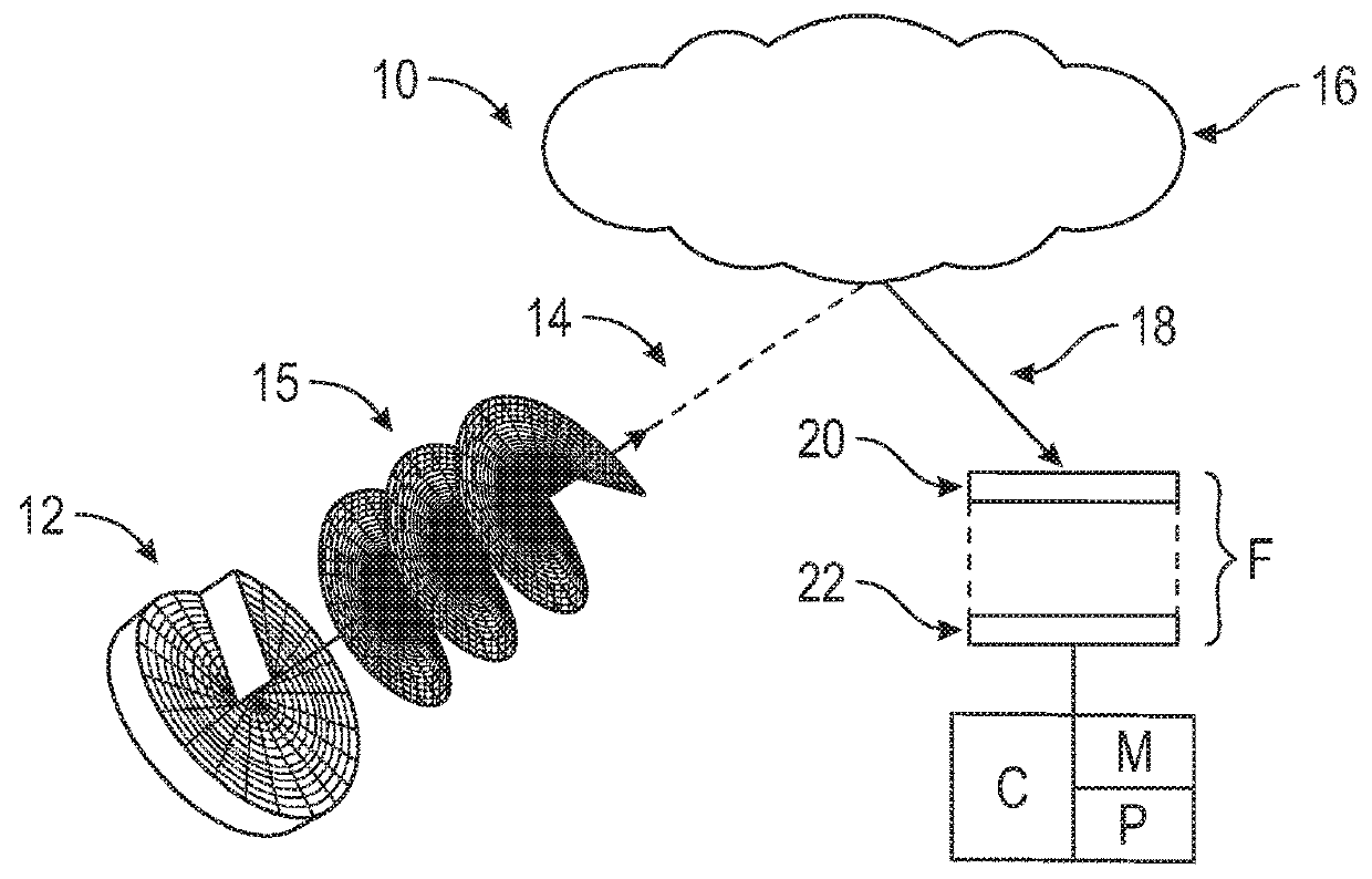
[0017]Referring to the Figures, wherein like reference numbers refer to the same or similar components throughout the several views, FIG. 1 is a schematic view of a remote sensing system 10. Referring...


PUM

PropertyMeasurementUnit
wavelengthaaaaaaaaaa
orbital angular momentumaaaaaaaaaa
diameteraaaaaaaaaa

Abstract

A remote sensing system includes a primary beam configured to carry orbital angular momentum and characterized by a mode number (m), with the mode number (m) being a non-zero integer. The primary beam is configured to be directed at a target. A photon sieve is configured to receive a secondary beam emanating from the target. The secondary beam at least partially includes a portion of the primary beam. The photon sieve includes a plurality of holes forming one or more respective spiral patterns. The quantity of the respective spiral patterns in the photon sieve corresponds to the mode number (m) of the primary beam. The plurality of holes may be configured to have a minimum diameter such that the minimum diameter is greater than a predefined wavelength of the primary beam. The respective spiral patterns extend between a respective first hole and a respective final hole.

Description

CROSS-REFERENCE TO RELATED PATENT APPLICATION(S)[0001]This patent application claims the benefit of and priority to U.S. provisional patent application 62 / 474,124, filed on Mar. 21, 2017, the contents of which are hereby incorporated by reference in their entirety.STATEMENT REGARDING FEDERALLY SPONSORED RESEARCH OR DEVELOPMENT[0002]The invention described herein was made in the performance of work under a NASA contract and by employees of the United States Government and is subject to the provisions of Public Law 96-517 (35 U.S.C. § 202) and may be manufactured and used by or for the Government for governmental purposes without the payment of any royalties thereon or therefore. In accordance with 35 U.S.C. § 202, the contractor elected not to retain title.BACKGROUND OF THE INVENTION[0003]Light Detection and Ranging (LIDAR) systems are often used to measure atmospheric, geologic, oceanic, biological and other properties of earth and various other celestial bodies. For example, LIDAR ...

Claims


Application Information

Patent Timeline
Patent Type & Authority Applications(United States)
IPC IPC(8): G02B5/18G01S17/89G01N21/21G01N21/55
CPCG02B5/188G01S17/89G01N21/21G01N21/55G01N2021/1793G02B5/005G01S7/4816
Inventor MACDONNELL, DAVID G.SUN, WENBOHU, YONGXIANG
Owner SCI SYST & APPL INC
Why Eureka
Try Eureka