Eureka AIR delivers breakthrough ideas for toughest innovation challenges, trusted by R&D personnel around the world.

Air conditioning system for motor vehicles

a technology for air conditioning systems and motor vehicles, which is applied in the direction of electrochemical generators, transportation and packaging, light and heating equipment, etc., can solve the problems of deteriorating comfort in the front seat region, sharp decrease in the cooling performance of the front seat air conditioning unit, and unstable temperature of the air discharged into the passenger compartment, so as to prevent a sudden change in the refrigerant flow rate, and prevent a sudden chang

Active Publication Date: 2018-10-04
HANON SYST
View PDF0 Cites 13 Cited by
  • Summary
  • Abstract
  • Description
  • Claims
  • Application Information

AI Technical Summary

Benefits of technology

This patent is about an air conditioning system for motor vehicles that prevents sudden changes in refrigerant flow rate when multiple air conditioning units are turned on simultaneously. Another goal is to prevent a decrease in cooling performance and sudden changes in temperature in the passenger compartment. Additionally, the system prevents a sudden change in refrigerant flow rate when one air conditioning unit is turned off in a state where the remaining units are still turned on.

Problems solved by technology

Thus, the temperature of the air discharged into the passenger compartment may become unstable.
This leads to a sharp decrease in the cooling performance of the front seat air conditioning unit 20.
As a result, the comfort in the front seat region is deteriorated.
Thus, the cooling performance of the front seat air conditioning unit 20 is excessively increased.
As a result, the comfort of the front seat region is significantly deteriorated.

Method used


Image

  • Air conditioning system for motor vehicles
  • Air conditioning system for motor vehicles
  • Air conditioning system for motor vehicles

Examples


first embodiment

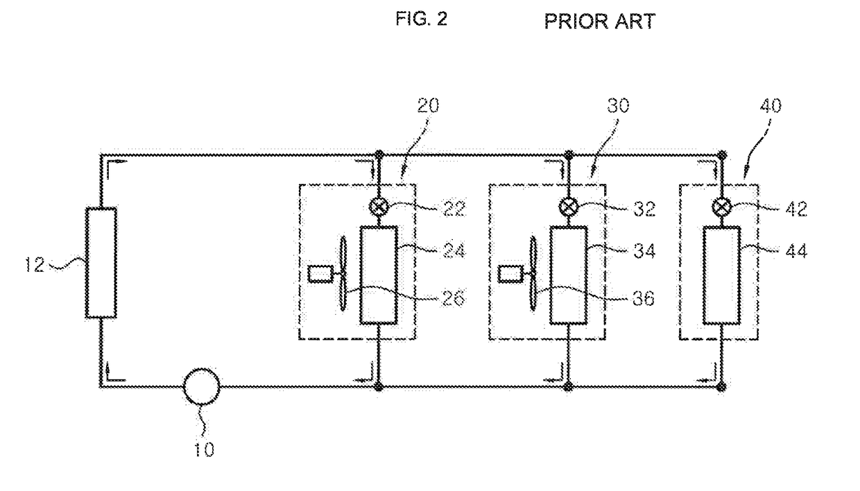
[0044]First, a multi-zone type air conditioning system will be briefly described with reference to FIG. 5 prior to describing features of the air conditioning system for motor vehicles according to the present invention.

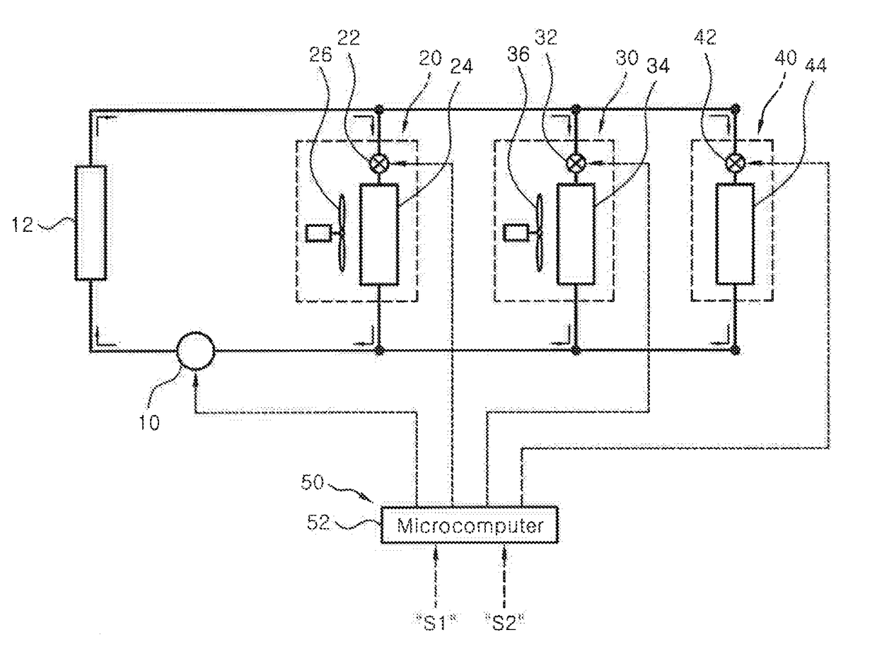
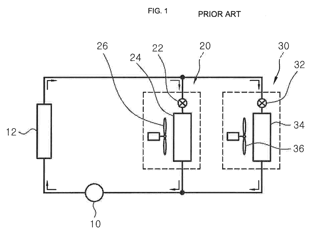
[0045]The multi-zone type air conditioning system includes a compressor 10, a condenser 12, a front seat air conditioning unit 20, a rear seat air conditioning unit 30 and a battery air conditioning unit 40. The front seat air conditioning unit 20, the rear seat air conditioning unit 30 and the battery air conditioning unit 40 are installed in parallel with each other with respect to the compressor 10 and the condenser 12.

[0046]The front seat air conditioning unit 20 is provided for cooling a front seat region in a passenger compartment, and includes an expansion valve 22, an evaporator 24 and a blower 26 for blowing a cold air of the evaporator 24 to the front seat region in the passenger compartment.

[0047]The rear seat air conditioning unit 30 is provided for cooli...

second embodiment

[0123]Next, the air conditioning system for motor vehicles according to a second embodiment of the present invention will be described with reference to FIG. 8.

[0124]The air conditioning system according to the second embodiment includes a control unit 50. The control unit 50 includes opening / closing valves 22-1, 32-1 and 42-1 integrally installed with the expansion valves 22, 32 and 42.

[0125]The opening / closing valves 22-1, 32-1 and 42-1 are installed on the upstream side of the expansion valves 22, 32 and 42. The opening / closing valves 22-1, 32-1 and 42-1 are on / off controlled in response to a control signal applied thereto, thereby cutting off or permitting a flow of a refrigerant to the expansion valves 22, 32 and 42.

[0126]If necessary, the opening / closing valves 22-1, 32-1 and 42-1 may be installed separately from the expansion valves 22, 32 and 42. In this case, the opening / closing valves 22-1, 32-1 and 42-1 are installed on the upstream side of the expansion valves 22, 32 and...


PUM


Abstract

An air conditioning system for motor vehicles includes a compressor, a condenser, a plurality of air conditioning units connected in parallel with each other with respect to the compressor and the condenser, and a flow rate control unit configured to, when a specific one of the air conditioning units is additionally turned on or is turned off, prevent occurrence of a sudden change in refrigerant amount in the remaining air conditioning units.

Description

CROSS-REFERENCE TO RELATED PATENT APPLICATIONS[0001]This application claims the benefit of each of Korean Patent Application No. 10-2017-0038401 dated Mar. 27, 2017 and Korean Patent Application No. 10-2017-0117564 dated Sep. 14, 2017. The disclosures of the above patent applications are hereby incorporated herein by reference in their entirety.TECHNICAL FIELD[0002]The present invention relates to an air conditioning system for motor vehicles, and more particularly, to an air conditioning system for motor vehicles which includes a plurality of air conditioning units for independently heating and cooling a plurality of regions of a passenger compartment. The air conditioning system is capable of preventing a sudden change in refrigerant flow rate in the remaining air conditioning units when one of the air conditioning units is additionally turned on or off and capable of preventing a decrease in cooling performance of the air conditioning units due to the sudden change in refrigerant...

Claims


Application Information

Patent Timeline
Patent Type & Authority Applications(United States)
IPC IPC(8): B60H1/32B60H1/00F25B5/02F25B41/20F25B41/31
CPCB60H2001/00949B60H2001/3289B60H2001/00928B60H1/00878B60H1/323B60H1/3223F25B5/02H01M10/613H01M10/615H01M10/625H01M10/663B60H1/00278B60H1/3204F25B49/022F25B2600/0253F25B2600/01F25B2700/2117F25B2600/2519F25B2600/2513F25B41/20F25B41/31F25B49/02F25B2600/23B60H1/3216B60H2001/3261B60H2001/3283B60H2001/3285Y02E60/10
Inventor BAEK, CHANG HYUNKIM, CHUL SOONKIM, TAE EUNMIN, SE WONYOO, SANG JUNJUNG, HONG RAEYOON, SEO JUNLEE, SEUNG HOLEE, JAE MINKIM, YOUNG CHULKIM, IN HYEOK
Owner HANON SYST
Why Eureka
Eureka Blog
Learn More