Gas turbine engine

a gas turbine engine and engine core technology, applied in the direction of machines/engines, sustainable transportation, mechanical equipment, etc., can solve the problems of high thermodynamic efficiency, relatively long engine cores, thin engine cores, etc., and achieve the effect of reducing bending, stiff and structurally efficient, and reducing engine flexing

Active Publication Date: 2018-10-04
ROLLS ROYCE PLC
View PDF0 Cites 11 Cited by
  • Summary
  • Abstract
  • Description
  • Claims
  • Application Information

AI Technical Summary

Benefits of technology

[0008]Accordingly, the structural load bearing second outer core case has a relatively straight profile through the compressor system, in spite of the relatively serpentine core working gas flow path through the low and high pressure compressors. This arrangement thereby provides a relatively stiff and structurally efficient structure, which in turn reduces bending for a given structural weight. In view of the stiff core structure, engine flexing is reduced in flight, thereby permitting reduced core rotor tip clearances, and improved reduction gearbox shaft and gear teeth alignment.

Problems solved by technology

High OPR results in high thermodynamic efficiency, and so low fuel burn.
However, high OPR engine cores (having a large number of compressor stages) and / or high bypass ratios can result in relatively long, thin engine cores.
Such cores can be susceptible to flexing in flight, which can result in rotor blade tip rubs (potentially resulting in damage) and / or excessive blade tip clearances being required (resulting in an adverse impact on efficiency).
Increasing the engine core stiffness by using additional bracing can result in engine weight penalties, which again detracts from the overall aircraft level reduction in fuel consumption provided by high bypass ratios and / or high OPR.

Method used


Image

  • Gas turbine engine
  • Gas turbine engine
  • Gas turbine engine

Examples


Embodiment Construction

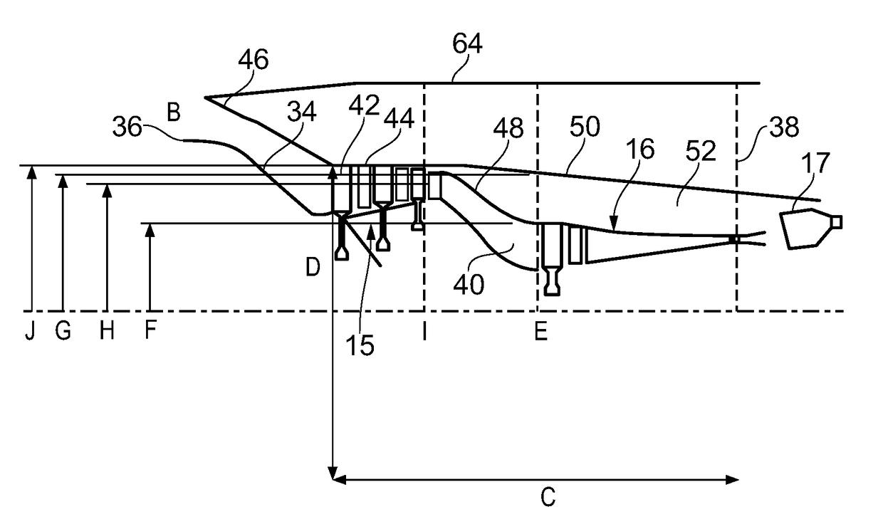
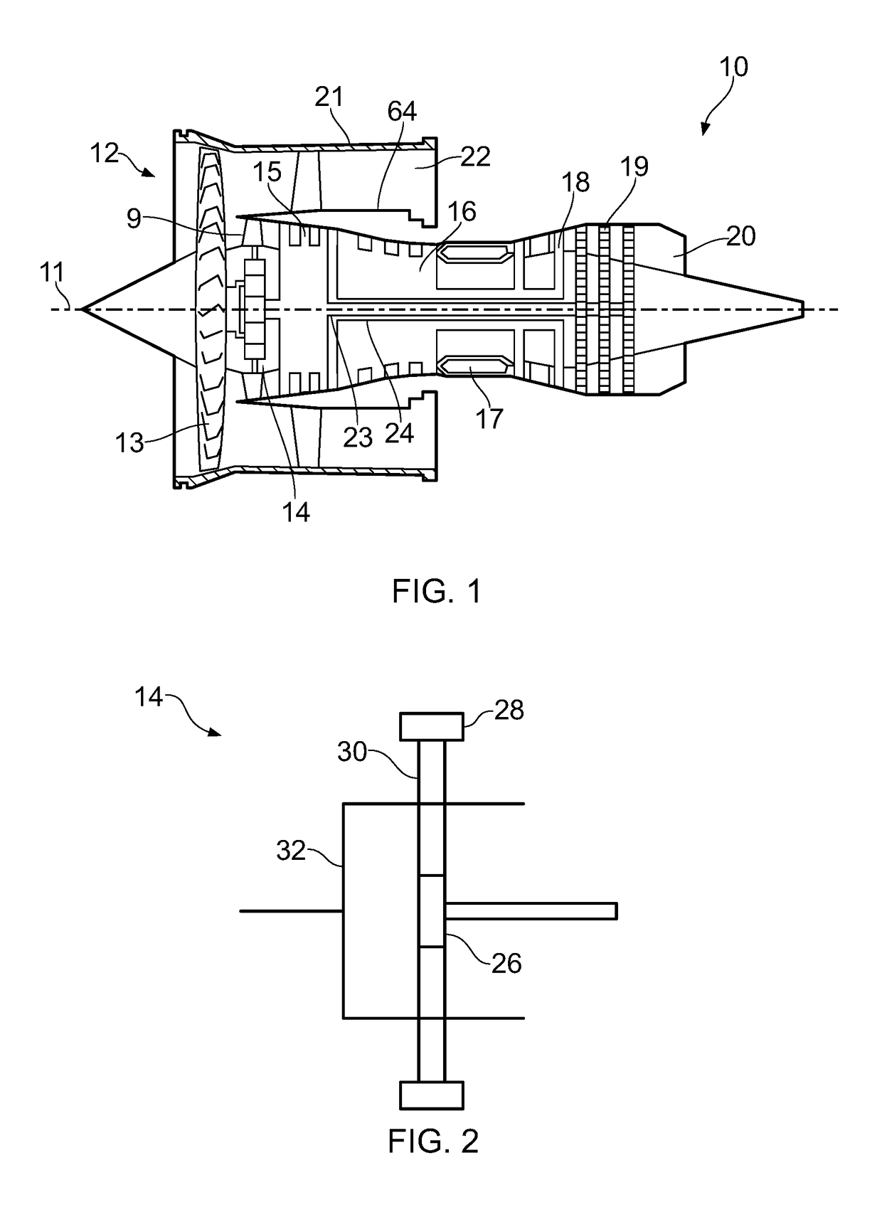
[0026]With reference to FIG. 1, a gas turbine engine is generally indicated at 10, having a principal and rotational axis 11. The engine 10 comprises, in axial flow series, an air intake 12, a propulsive fan 13, a low pressure compressor 15, a high pressure compressor 16, combustion equipment 17, a high pressure turbine 18, a low pressure turbine 19 and a core exhaust nozzle 20. A nacelle 21 generally surrounds the engine 10 and defines the intake 12. A bypass passage inner casing 64 is also provided, which is spaced radially inwardly from the nacelle 21, and defines a bypass passage therebetween.

[0027]The gas turbine engine 10 works in the conventional manner so that air entering the intake 12 is accelerated by the fan 13 to produce two air flow paths: a first air flow path A into the core 9 of the engine, the low pressure compressor 15, the high pressure compressor 16 and downstream components, as a core flow; and a second air flow path B which passes through a bypass duct 22 to p...


PUM


Abstract

A gas turbine engine (10) includes: a compressor system comprising a low pressure compressor (15) and a high pressure compressor (16) coupled to low pressure and high pressure shafts, respectively (23, 24); an inner core casing (34) provided radially inwardly of compressor blades (42), and an outer core casing provided outwardly of compressor blades, the inner core casing and outer core casing defining a core working gas flow path (B) therebetween; a fan (13) coupled to the low pressure shaft via a gearbox (14); wherein the outer core casing comprises a first outer core casing (48) and a second outer core casing (50) spaced radially outwardly from the first outer core casing, and wherein at an axial plane (E) of an inlet to the high pressure compressor, the second outer core casing has an inner radius at least 1.4 times the inner radius of the first outer core casing.

Description

CROSS-REFERENCE TO RELATED APPLICATION[0001]This application is based upon, and claims the benefit of priority from UK Patent Application No. 1704173.2, filed on 16 Mar. 2017, the entire contents of which are hereby incorporated by reference.BACKGROUNDField[0002]The present disclosure concerns a geared aircraft gas turbine engine.Description of Related Art[0003]Aircraft gas turbine engines typically comprise a gas turbine engine core and a core driven fan enclosed within a fan nacelle. Air flows through the fan in use, and is divided into two airflows downstream—a bypass flow and a core flow. The ratio between the mass flow rate of air in the bypass flow to the mass flow rate of airflow of the core flow is known as the bypass ratio. At subsonic flight velocities, a large bypass ratio is desirable for high efficiency.[0004]Gas turbine engine efficiency can also be increased by increasing the Overall Pressure Ratio (OPR). High OPR results in high thermodynamic efficiency, and so low f...

Claims


Application Information

Patent Timeline
Patent Type & Authority Applications(United States)
IPC IPC(8): F02C7/36F01D25/24F02C9/18
CPCF05D2220/3216F02C7/36F02C9/18F05D2240/60F05D2220/323F01D25/24F02K3/06Y02T50/60
Inventor POINTON, JAMES M.BRADBROOK, STEPHEN J.
Owner ROLLS ROYCE PLC
Why Eureka
Try Eureka