Regulation Method for Inverter Compressors in Refrigeration Facilities

a technology of inverter compressor and refrigeration facility, which is applied in the direction of climate sustainability, sorption machine, light and heating apparatus, etc., can solve the problems of heat generated in the condenser, loss in the system,

Active Publication Date: 2018-10-04
AVILA CHILLIDA VICENTE
View PDF13 Cites 7 Cited by
  • Summary
  • Abstract
  • Description
  • Claims
  • Application Information

AI Technical Summary

Problems solved by technology

The problem with this model is that the cooling liquid flows through the entire circuit, thus causing loses in the system due to joins in the communications.
In both systems, the problem comes from the heat generated in the condensers, which heat the same area that is to be cooled.

Method used


Image

  • Regulation Method for Inverter Compressors in Refrigeration Facilities
  • Regulation Method for Inverter Compressors in Refrigeration Facilities
  • Regulation Method for Inverter Compressors in Refrigeration Facilities

Examples


Embodiment Construction

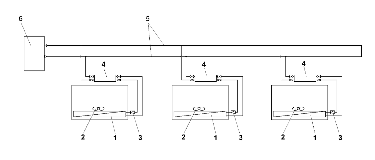
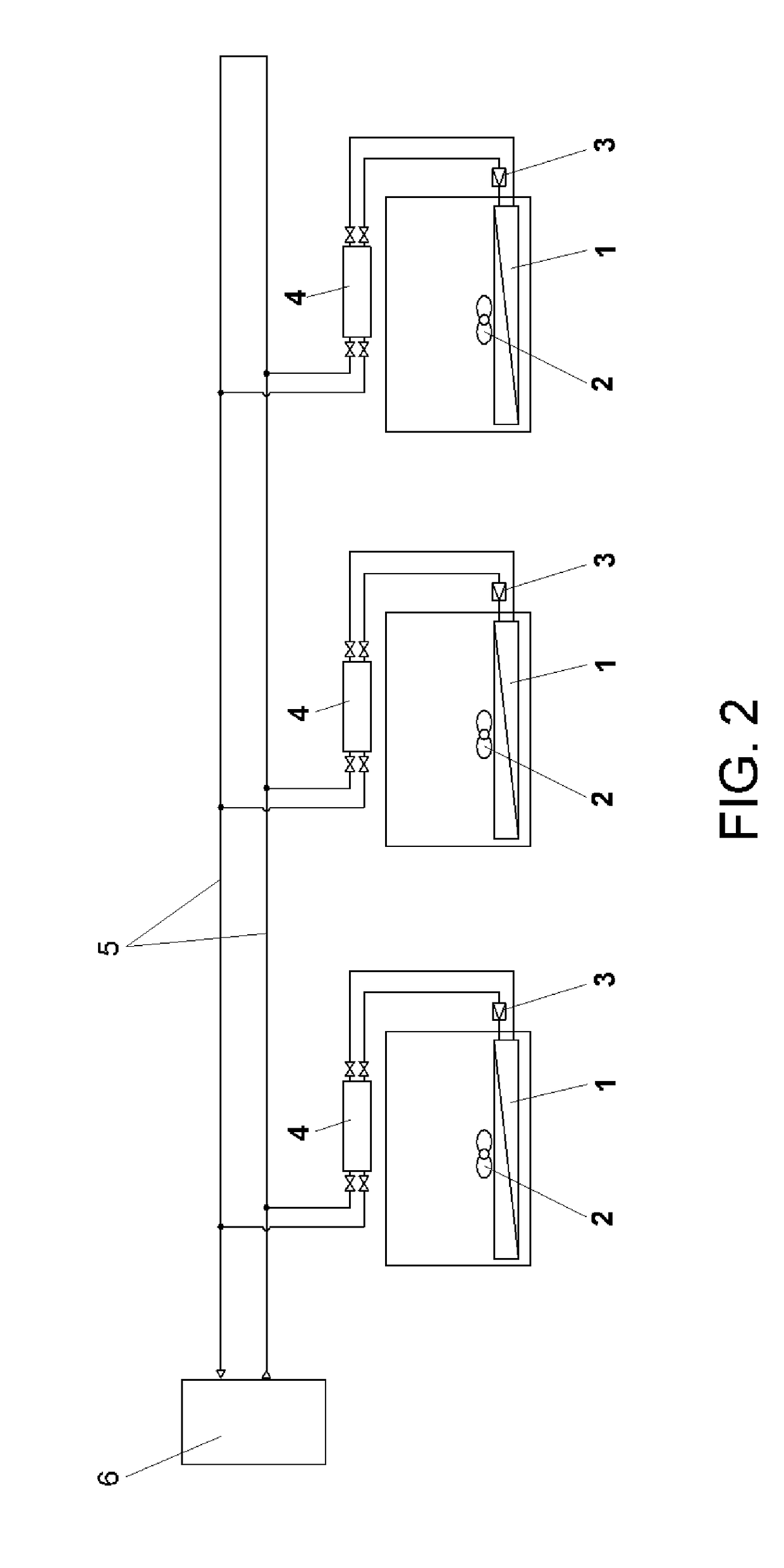
[0068]In a preferred embodiment and as shown in FIG. 2, the system includes a water ring (5) connected to a heat dissipater (6). Branches extend from the water ring (5) to the heat exchangers (8) of the condensers of the different refrigerating units (4) that make up the respective refrigeration equipment of the system, where the water receives the heat from the coolant. As for the coolant, the refrigerating units (4) are connected to the evaporators (1) through the expansion valves (3).

[0069]The system can use any of the substances known in the state of the art such as, for example, HFC, ammonia, propane, or even CO2, as coolant.

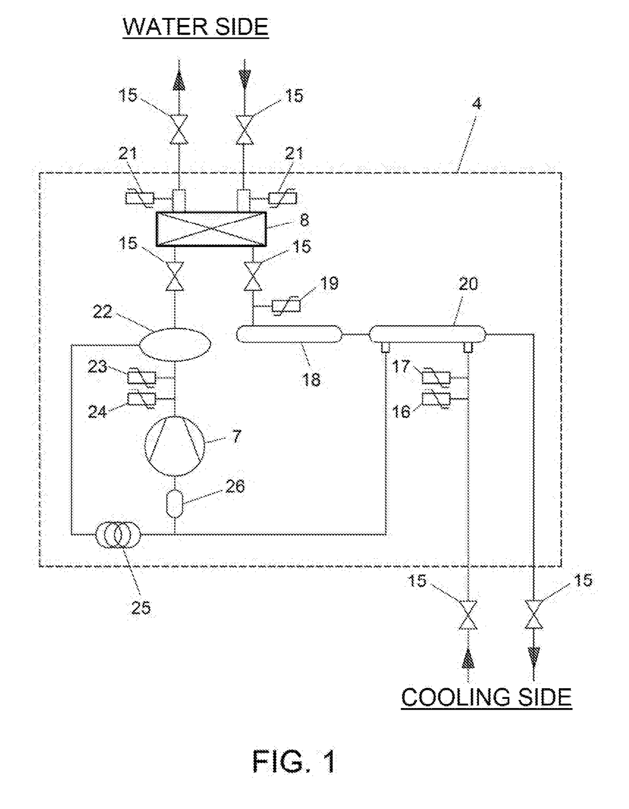
[0070]FIG. 2 shows how the water from the closed ring (5) comes in and out of the heat exchanger (8) of each of the refrigerating units (4) controlled by both water temperature probes (21), as shown in FIG. 1.

[0071]FIG. 1 represents the refrigerator diagram of a refrigerating unit (4) using an inverter compressor (7). The inverter compressors (7) do not sto...


PUM


Abstract

A regulation method for an inverter compressor in a refrigeration system including establishing a working area via limit values for evaporation temperatures, condensation temperatures, compressor speeds, maximum compression ratio, and maximum reheat value, and measuring working values of the compressor in terms of evaporation temperature, condensation temperature, and compression ratio. If the compressor operates outside the established working area, the method includes modifying the working parameters of the compressor by acting on elements to be selected among the compressor speed, the opening angle of the expansion valve, and a combination thereof. If the compressor does not go back to the working area within a certain time, the method includes stopping operation of the compressor and triggering an alarm.

Description

CROSS-REFERENCE TO RELATED APPLICATION[0001]This application claims priority to Spanish Patent Application No. P201700309 filed Mar. 29, 2017, the disclosure of which is hereby incorporated in its entirety by reference.BACKGROUND OF THE INVENTIONField of the Invention[0002]The present invention relates to controlling the refrigerating unit in refrigeration equipment by regulating the inverter compressor, both on an individual basis and for the system as a whole.Description of Related Art[0003]In most of the existing systems there are two situations that divide the current technology.[0004]The first is a refrigeration system consisting of a central unit from which the entire refrigeration cycle is carried out. These systems have a series of centralised compressors and condensers that are of the appropriate size to be able to generate the amount of refrigeration needed to reach the working conditions in the specified area.[0005]The other system consists of having a centralised area an...

Claims


Application Information

Patent Timeline
Patent Type & Authority Applications(United States)
IPC IPC(8): F25B49/02F25B41/06F25B49/04F25B15/00
CPCF25B49/025F25B41/062F25B49/043F25B15/006F25B2600/021F25B2600/0253F25B2341/06F25B2313/0314F25B2313/0315F25B49/005F25B2500/19F25B2600/0251F25B2600/19F25B2600/21F25B2600/2513F25B2700/1931F25B2700/21152F25B2700/21174F25B2700/21175Y02B30/70
Inventor AVILA CHILLIDA, VICENTE
Owner AVILA CHILLIDA VICENTE
Why Eureka
Try Eureka